==== An open-source EV conversion VCU (vehicle control unit) for controlling salvaged EV components! ====
*A fully tested V1a kit is now available for general sale [https://www.evbmw.com/index.php/evbmw-webshop/vcu-boards/zombie-vcu here]. The boards are now shipping with the Wemos wifi module and all parts will be included in the kit. The Olimex header is still there for those who may prefer that option. See [https://openinverter.org/forum/viewtopic.php?p=48250#p48250] for the Wemos wifi module mounting location.
* '''[https://openinverter.org/forum/viewtopic.php?f=3&t=1277 Development thread]'''
Modern EV conversion projects often look to reuse salvaged parts from wrecked vehicles, such as the motors, batteries and chargers.
The issue is that each of these components and manufacturers, use different methods of control and communication.
Developing controllers for these devices is complex, and time consuming and often require very dedicated communication protocols. Instead of making custom boards for every part that's been decoded, why not just make a general purpose VCU (vehicle control unit) with a verity of different types of inputs and outputs?
==== '''Introducing: the "ZombieVerter" VCU ''- a general purpose EV conversion VCU.''''' ====
With a large array of inputs/outputs, control logic, and a web interface for configuration and data logging. The ZombieVerter is a powerful, flexible and customizable VCU well suited for EV conversions.
It's also an open source project!
==== The ZombieVerter supports popular salvaged EV parts such as: ====
* Nissan Leaf components
* Mitsubishi Outlander hybrid components
* Toyota and Lexus hybrid components
* CHAdeMO and CCS DC fast charging
* and more!
==== The ZombieVerter features the following: ====
==== Hardware: ====
* On-board WiFi
* 3x high side PWM drivers
* 5x low side outputs
* 3x input pins (pull to ground only)
* 3x CANbus interfaces
* LIN bus
* sync serial interface
* OBD-II interface
* etc.
==== Software: ====
* Web based user interface
* Contactor control
* Charger control
* Charge timer
* Motor (inverter) control
* Heater control
* Water pump control
* Coolant fan control
* Throttle mapping
* Motor regen
* Cruise control (?)
* BMS limits
* IVT shunt initialization
* Data logging and graphing
* etc.
=== Currently supported OEM hardware: ===
<nowiki>*</nowiki>This list is always growing and changing, and not everything is verified working
==== Motors/Drive units: ====
* [[Nissan leaf motors|Nissan Leaf Gen1/2/3 inverter/motor via CAN]]
*''Unless you have a specific reason not to, end users should use a software release from https://github.com/damienmaguire/Stm32-vcu/releases<nowiki/>.''
===== Cars(for canbus control over dash, etc): =====
|}
* 1998-2005 BMW 3-series (E46) CAN support
* 1996-2003 BMW 5-series (E39) CAN support
* 2001-2008 BMW 7-series (E65) CAN Support
* BMW E9x CAN support
* Mid-2000s VAG CAN support
* Subaru CAN support
== Assembling the VCU ==
Looking to build a ZombieVerter VCU yourself or the kit is missing hardware?
* [[Zombiverter hardware]] page for additional build instructions
* [https://github.com/damienmaguire/Stm32-vcu Github with PCB, schematic, pin-outs, etc]
''The enclosure and header are required if you did not order a [https://www.evbmw.com/index.php/evbmw-webshop/vcu-boards/zombieverter-vcu-built '''fully built board''']''
VCU boards from the webshop, '''''come pre-programmed''''' and '''do not require any additional steps taken to work'''.
For programming a blank board see: [[zombieverter programing|ZombieVerter programming]]
===The enclosure kit options:===
# [https://www.aliexpress.com/item/32857771975.html?spm=a2g0s.9042311.0.0.39f24c4dWOmGPE Enclosure Kit with Header, connector and pins]<ref>https://www.aliexpress.com/item/32857771975.html?spm=a2g0s.9042311.0.0.39f24c4dWOmGPE (Backup: [https://web.archive.org/web/20220524004318/https://www.aliexpress.com/item/32857771975.html Web Archive])</ref>
#[https://www.aliexpress.com/item/32822692950.html Connector and pins]<ref>https://de.aliexpress.com/item/32822692950.html (Backup: [https://web.archive.org/web/20221119203700/https://www.aliexpress.us/item/2251832636378198.html?gatewayAdapt=glo2usa4itemAdapt&_randl_shipto=US Web Archive])</ref>
#[https://www.aliexpress.com/item/1005003512474442.html Pre-wired connector] <ref>https://www.aliexpress.com/item/1005003512474442.html (Backup: [http://web.archive.org/web/20221120105651/https://www.aliexpress.us/item/3256803326159690.html?gatewayAdapt=glo2usa4itemAdapt&_randl_shipto=US Web Archive])</ref>
[[File:ZombieVerter VCU V1 cable side pinout2.jpg|thumb|alt=|VCU pinout diagram |513x513px]]Each device requires different wiring setups, settings and power requirements.
<nowiki>*</nowiki>cross referencing OEM wiring diagrams is highly recommended
'''Development continues''' and you can
'''Wiring the ZombieVerter with:'''
[https://openinverter.org/forum/viewtopic.php?f=3&t=1277 follow and contribute along with the development here on the forum]
[https://openinverter.org/forum/viewtopic.php?f=3&t=1696 '''Support''' is available via a separate thread on the forum]
* [[GS450H with zombieverter|GS450H with ZombieVerter]]
* [[Leaf stack with zombiverter|Leaf stack with ZombiVerter]]
* [[Tesla SDU with Zombieverter|Tesla SDU with ZombieVerter]]
* [[Chademo with Zombieverter]]
==Introduction ==
=== Power wiring ===
Rather than crack open inverters and swap components about to drive them, what if we simply send them the messages they're expecting? This has been the case with a couple of existing designs (Nissan leaf inverter and GS450h) and thanks to the SAM3X8E microcontroller no longer being stocked by JLCPCB this project looks to take it further.
The ZombieVerter requires a permanent 12V supply. This is so it can manage charging, timers, and monitor systems when the car is at rest.
The average power draw, at idle, is 150 mA.
* Pin 55 to 12V- ground
* Pin 56 to 12V+ positive
So rather than driving an inverter powerstage this version sends CAN for the Leaf inverter or Sync serial for the GS450h and of course can be expanded to any number of others. This will be the default firmware for all VCU products from now on and future hardware will support future fun packed stuff like FLEXRAY!!!
The ZombieVerter controls power/"ignition" signals to other devices (inverters, chargers, and DCDC converters), powering those devices when required. This is done by triggering an external 12V relay. '''''ZombieVerter controls the external relay using low-side switching'', meaning that it pulls the ground pin of the relay to ground.'''
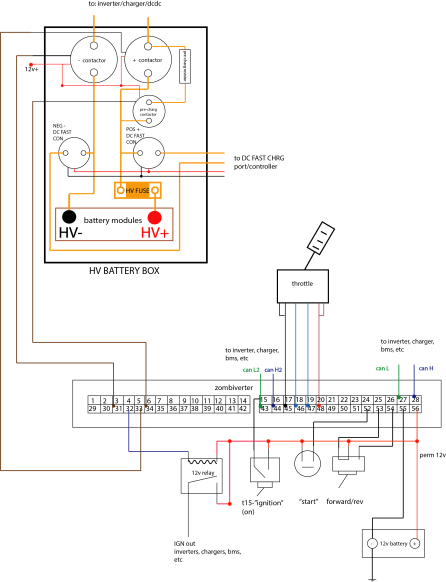
* [[File:Gernice-zombie.png|thumb|583x583px|general zombie and battery box wiring]]Pin 32 to ground pin on a 12V relay
* Relay positive pin to 12V+
* One of the relays switch pin to 12V+
It's basically an <s>rip off</s> homage and builds on other people's hard work in the shape of the following projects
This effectively provides a switched 12V supply, controlled by the ZombieVerter.
*[https://github.com/Isaac96/SimpleISA ISA library]
*Leaf inverter driver by Celeron55
* Leaf inverter enable pin
* Leaf PDM enable pin
* Mitsubisihi OBC enable pin
What we have as of now is the openinverter wrapper with things like :
=== Contactor wiring ===
The Zombieveter manages the Negative, Positive and PreCharge contactors in an EV conversion.
*Throttle cal and mapping,
This is done based off a series of voltage measurements (UDC), this voltage value (UDC) can be supplied from a variety of sources:
*Precharge and contactor control,
*Temp derating,
*BMS limits,
*for/rev/neutral control,
*Graphing and monitoring,
*Firmware updates via the web interface,
*Cruise control,
*Fuel gauge driver,
*etc
==Hardware==
* ISA IVT shunt
[[File:Zombv1boardb.jpg|thumb|alt=|Location of remaining parts]]
* Nissan leaf inverter
So you've ordered your kit, first things first, watch the following two videos to assemble it.
* BMW S-BOX
* etc.
Due to chip shortages (written summer 2021) the board isn't fully assembled so you will need to do some soldering, or take it to a local phone repair shop (or similar) who'll find soldering at this scale like playing with Duplo (Legos to you Yanks).
''Without a proper UDC measurement, the ZombieVerter '''will fail precharge and never go into run mode.'''''
{| class="wikitable"
|+Parts to be fitted to ZombieVerter VCU
!Name
!Part Numer
!Alternative Part Number
|-
|CONN1
|
|
|-
|IC10
|MCP25625T
|
|-
|IC14
|TJA1020
|MCP2004
|-
|IC19
|NCV7356
|
|-
|IC20
|TJA1055T
|
|-
| IC21, IC22
|AD5160
|
|-
|IC27, IC28, IC29
|FAN3122
|
|}
===The enclosure kit links===
You only need one, but below are two options - one with just the connector, and the other prewired with 3M long leads.
*Enclosure Kit with Header, connector and pins: [https://www.aliexpress.com/item/32857771975.html?spm=a2g0s.9042311.0.0.39f24c4dWOmGPE Link to Aliexpress]
'''The contactor control pins on the ZombieVerter are ''low-side switching'', meaning that they pull to ground.'''
*Prewired connector with 3M leads (limited colors which will not match standard wire colouring conventions): [https://www.aliexpress.com/item/4001213569338.html?spm=a2g0o.cart.0.0.366c3c00qhBvGO&mp=1 Link to Aliexpress]
The positive leads from the contactors need to be connected to 12V+ and the ground leads to:
The kits do not come with M3 screws needed to secure the board to the enclosure (2 need to be slightly longer), and to secure the lid. Nor a gasket for the lid.
* Pin 31 for the negative contactor
* Pin 33 for the positive contactor
* Pin 34 for the pre-charge contactor
=== Throttle pedal wiring ===
The ZombieVerter supports dual-channel throttle. This redundancy is for safety in case one channel fails or drops out. It's highly recommended to use dual-channel throttle. Single-channel is an option.
Connect the following to the ZombieVerter pins:
'''Note that in addition to the VCU, the inverter and transmission, you will require a specific CANBUS connected shunt''': [[Isabellenhütte Heusler]]
* Pin 45 to throttle grounds
* Pin 46 to throttle channel 2
* Pin 47 to throttle channel 1
* Pin 48 to throttle positives
=== Start, Run, and Direction wiring ===
The ZombieVerter requires 2 inputs to get into "drive" mode. '''These pins need to be ''pulled high'' (connected to 12V +)'''
===Build and Configuration Videos===
* Pin 15 to "on" switched input (key switched to "on")
'''00:33''' Warning and suggestion to go watch cat videos instead<br />
'''[https://youtu.be/geZuIbGHh30?t=66s 01:06]''' Recap about the ZombieVerter VCU Build Part 1<br />
'''[https://youtu.be/geZuIbGHh30?t=184s 03:04]''' How to get one<br />
'''[https://youtu.be/geZuIbGHh30?t=215s 03:35]''' Design files currently require E10 Patreon membership/contribution if wanting to build your own<br />
'''[https://youtu.be/geZuIbGHh30?t=268s 04:28]''' Components still requiring soldering<br />
'''[https://youtu.be/geZuIbGHh30?t=303s 05:03]''' IC19 - 8 pin SOIC for single wire CAN (NCV7356)<br />
||
'''[https://youtu.be/geZuIbGHh30?t=360s 06:00]''' IC10 - SPI CAN controller and transceiver (MCP25625T)<br />
'''[https://youtu.be/MUhs9j9R9Mg?t=200s 03:20]''' Pinouts of the 56 pin connector<br />
'''[https://youtu.be/MUhs9j9R9Mg?t=256s 04:16]''' Pins 55,56 - Ground and +12V<br />
'''[https://youtu.be/MUhs9j9R9Mg?t=289s 04:49]''' Pins 53,54 - Reverse and Forward Direction. Apply +12V to the pin for the direction needed.<br />Configurable in the web interface to flip these since direction is relative<br />
'''[https://youtu.be/MUhs9j9R9Mg?t=452s 07:32]''' Pins 52 - Start. Momentarily apply +12V to send a start signal<br />
'''[https://youtu.be/MUhs9j9R9Mg?t=495s 08:15]''' Pin 51 - HV Request. Apply +12v to precharge and bring up the high voltage system<br /> (and not the drive components)<br />
'''[https://youtu.be/MUhs9j9R9Mg?t=545s 09:05]''' Pin 50 - General Purpose 12V Input. Reserved for future use<br />
'''[https://youtu.be/MUhs9j9R9Mg?t=563s 09:23]''' Pin 49 - Brake Input. Connect to brake light switch to apply +12V signaling brakes are applied<br />
'''[https://youtu.be/MUhs9j9R9Mg?t=615s 10:15]''' Pins 45,46,47,48 - Throttle. +5V power, ground, and 1 or 2 hall effect sensor inputs<br />
||
'''[https://youtu.be/MUhs9j9R9Mg?t=660s 11:00]''' Pins 25,26,27,28 - 3 CAN bus interfaces. CAN EXT is for vehicle/body communication,<br /> CAN EXT 2 for the ISA shunt comms,<br /> CAN EXT 3 (with solderable jumpers to change modes) is for general purpose like charger, heater control<br />
'''[https://youtu.be/MUhs9j9R9Mg?t=885s 14:45]''' Pin 24 - Local Interface Network (LIN)<br />
'''[https://youtu.be/MUhs9j9R9Mg?t=956s 15:56]''' Pins 16,17,18,19,20,21,22,23 - Toyota Hybrid Inverter specific using async serial comms.<br />
'''[https://youtu.be/MUhs9j9R9Mg?t=1041s 17:21]''' Pin 15 - Ignition T15 In. Apply +12V to turn Ignition on. Puts VCU in run mode<br />
'''[https://youtu.be/MUhs9j9R9Mg?t=1182s 19:42]''' Pins 35,36 - POT1 & POT2. Digital potentiometer outputs to drive analog gauges (fuel, etc)<br />
'''[https://youtu.be/MUhs9j9R9Mg?t=1270s 21:10]''' Pins 32,33,34 - Low Side (LS) switches for Inverter Power, Positive side Main Contactor, Precharge Contactor<br />
'''[https://youtu.be/MUhs9j9R9Mg?t=1401s 23:21]''' Pin 31 - General Purpose +12V Output. LS switch for Negative side Main Contactor<br />
'''[https://youtu.be/MUhs9j9R9Mg?t=1441s 24:01]''' Pins 12,13,14,29,30 - Toyota Hybrid System controls<br />
'''[https://youtu.be/MUhs9j9R9Mg?t=1524s 25:24]''' Pins 10,11 - Digital to Analog Converter (DAC) 1 & 2. Reserved for future use - additional analog instruments etc.<br />
'''[https://youtu.be/MUhs9j9R9Mg?t=1593s 26:33]''' Pins 8,9 - 0-5V Analog Inputs 1 & 2. Reserved for future use (ie not implemented yet)<br />
'''[https://youtu.be/MUhs9j9R9Mg?t=1626s 27:06]''' Pins 5,6,7 - Pulse Width Modulation (PWM) 1-3 +12V output signals. Reserved for future use (ie not implemented yet)<br />
'''[https://youtu.be/MUhs9j9R9Mg?t=1676s 27:56]''' Pins 3,4 - General Purpose +12V Outputs 2 & 3. Reserved for future use (ie not implemented yet)<br />
'''[https://youtu.be/MUhs9j9R9Mg?t=1709s 28:29]''' Pins 1,2 - RS232 Rx/Tx Serial connection for alternation VCU communication (solder jumper configurable). Reserved for future expansion<br />
'''[https://youtu.be/MUhs9j9R9Mg?t=1811s 30:11]''' CAN bus connected Isabellenhutte Huesler Shunt<br />
'''[https://youtu.be/MUhs9j9R9Mg?t=2325s 38:45]''' Web Interface<br />
'''[https://youtu.be/MUhs9j9R9Mg?t=2650s 44:10]''' How to perform a software update via the web interface using a precompiled binary<br />
'''[https://youtu.be/MUhs9j9R9Mg?t=2852s 47:32]''' UI Features - Commands<br />
'''[https://youtu.be/MUhs9j9R9Mg?t=3170s 52:50]''' UI Features - Update<br />
'''[https://youtu.be/MUhs9j9R9Mg?t=3210s 53:30]''' UI Features - Parameters<br />
'''[https://youtu.be/MUhs9j9R9Mg?t=4290s 1:11:32]''' UI Features - Spot Values<br />
'''[https://youtu.be/oPb4vMO17B4?t=426s 07:06]''' 12V battery - negative to chassis ground with fuse, and ground to VCU pin 55<br />
'''[https://youtu.be/oPb4vMO17B4?t=472s 07:52]''' 12V battery - positive to PDM positive terminal and distribution block<br />
'''[https://youtu.be/oPb4vMO17B4?t=522s 08:42]''' 12V battery - permanent fused +12v from PDM positive terminal to inverter and PDM<br />
'''[https://youtu.be/oPb4vMO17B4?t=554s 09:14]''' 12V battery - permanent fused +12v to vcu, relay controlled by VCU for switched +12v to inverter and PDM<br />
'''[https://youtu.be/oPb4vMO17B4?t=657s 10:57]''' 12V battery - permanent fused +12v to switch to provide things like T15 on signal to VCU<br />
'''[https://youtu.be/oPb4vMO17B4?t=762s 12:42]''' Other end of permanent 12v feed to inverter and PDM connections<br />
'''[https://youtu.be/oPb4vMO17B4?t=803s 13:23]''' Other end of switched +12v feed to inverter and PDM connections<br />
'''[https://youtu.be/oPb4vMO17B4?t=816s 13:36]''' Other end of switched 12v ground connection<br />
'''[https://youtu.be/oPb4vMO17B4?t=838s 13:52]''' Twisted pair wires from EV CAN CAN EXT 2 High (pin 28) and CAN EXT 2 Low (pin 27) to inverter<br />
'''[https://youtu.be/oPb4vMO17B4?t=946s 15:46]''' To use the PDM for charging, wire control pilot (CP) and plug present (PP) from PDM to charge socket<br />
'''[https://youtu.be/oPb4vMO17B4?t=989s 16:29]''' High voltage setup and controlling it with the VCU<br />
'''[https://youtu.be/oPb4vMO17B4?t=1028s 17:08]''' Positive and precharge contactors (only 2 for the test rig - usually would have a negative contactor as well)<br />
'''[https://youtu.be/oPb4vMO17B4?t=1060s 17:40]''' High voltage positive and negative junction. The ISA shunt connected between negative and PDM to distribute high voltage negative to the components<br />
'''[https://youtu.be/oPb4vMO17B4?t=1093s 18:13]''' V1 ISA shunt connection to PDM after the contactors/precharge system to monitor high voltage applied to the drivetrain<br />
<u>Low side Outputs.</u>
'''[https://youtu.be/oPb4vMO17B4?t=1131s 18:51]''' Contactor control using negative side connections via VCU (very brief description)<br />
||
'''[https://youtu.be/oPb4vMO17B4?t=1315s 21:55]''' Leaf PDM Internals, starting with high voltage connections<br />
'''[https://youtu.be/oPb4vMO17B4?t=1388s 23:08]''' Leaf PDM Internals, single phase AC charging connections<br />
'''[https://youtu.be/oPb4vMO17B4?t=1438s 23:49]''' CCS type 2 socket connections<br />
'''[https://youtu.be/oPb4vMO17B4?t=1490s 24:50]''' Gome Cat comes in to say hello<br />
'''[https://youtu.be/oPb4vMO17B4?t=1545s 25:45]''' Control switches. +12v, forward input, terminal 15 input, start input, high voltage request input. <br />
'''[https://youtu.be/oPb4vMO17B4?t=1584s 26:24]''' Step 1 is close switch providing +12v to the forward input and T15 connections to enable "ignition on" mode<br />
'''[https://youtu.be/oPb4vMO17B4?t=1605s 26:45]''' Step 2 is toggle start input to activate precharge, closing of main contactor, and inverter main relay (assuming all conditions are met)<br />
'''[https://youtu.be/oPb4vMO17B4?t=1645s 27:25]''' Example throttle from mid 2000s BMW. Two channel hall effect sensor<br />
'''[https://youtu.be/oPb4vMO17B4?t=1726s 28:46]''' Charging description when plugging in charger cable<br />
'''[https://youtu.be/oPb4vMO17B4?t=1771s 29:31]''' Throttle Calibration using spot values for '''pot''' and '''pot2''' in auto refresh mode while pressing the pedal across it's range, noting the min/max and recording the min+10 for '''potmin''', and max-10 for '''potmax''' for each pot under parameters. Also select dual channel '''potmode''' if using two channels (will not work in single channel mode with 2 channels wired up)<br />
'''[https://youtu.be/oPb4vMO17B4?t=2257s 37:37]''' Running the motor<br />
'''[https://youtu.be/oPb4vMO17B4?t=2864s 47:44]''' Problems/gotchas - '''PRECHARGE''' error (no high voltage supply, '''udc''' not > '''udcsw''' within 5s)<br />
'''[https://youtu.be/oPb4vMO17B4?t=3016s 50:16]''' Problems/gotchas - too high '''udcmin''' setting and no motor spin, '''potum''' will not go positive<br />
'''[https://youtu.be/oPb4vMO17B4?t=3239s 53:59]''' Problems/gotchas - too low '''udcmax''' (max voltage to allow regen) - motor spins without slowing when throttle released<br />
'''[https://youtu.be/oPb4vMO17B4?t=3373s 56:13]''' Explanation of '''udclim''' as redundant cutoff voltage to shut off contactors<br />
'''[https://youtu.be/oPb4vMO17B4?t=3400s 56:40]''' Explanation of '''idcmax''' and '''idcmin''' current limits<br />
'''[https://youtu.be/oPb4vMO17B4?t=3420s 57:00]''' Explanation of '''tmphsmax''' heatsink max temp too low, and min setting allowed of 50C<br />
'''[https://youtu.be/oPb4vMO17B4?t=3548s 59:08]''' Problems/gotchas - '''throtmax''' too low, no motor spin<br />
'''[https://youtu.be/oPb4vMO17B4?t=3706s 1:01:46]''' Charging example using '''Leaf_PDM''' - seems incomplete, see below<br />
'''[https://youtu.be/oPb4vMO17B4?t=3780s 1:03:00]''' Wifi Connection to the VCU and upgrading firmware<br />
'''[https://youtu.be/oPb4vMO17B4?t=3983s 1:06:23]''' Resolve update fail/hang - activity led stops flashing, no data on web interface (power cycle)<br />
'''[https://youtu.be/oPb4vMO17B4?t=4225s 1:10:25]''' Gome cat in it's natural habitat<br />
'''[https://youtu.be/oPb4vMO17B4?t=4399s 1:13:19]''' Causes of wifi issues<br />
'''[https://youtu.be/oPb4vMO17B4?t=4609s 1:16:49]''' Initializing the ISA shunt<br />
'''Pin Out Diagram'''[[File:ZombieVerter VCU V1 cable side pinout.jpg|thumb|alt=|VCU pinout diagram |none]]
*GP Out 2
[[File:Zomb-con-et.png|none|thumb|List of connections to system components (GS450 application)]]
* Neg Contactor switch/GP Out 1
*Trans SL1- (If not using the GS450H)
*Trans SL2- (If not using the GS450H)
'''*Low side output connect to ground when activated.'''
Further information for a GS450 system can be found here: [[Lexus GS450h Drivetrain]]
The low side outputs in Zombie are ideal for switching relays, such as for coolant pumps.
'''Note''': In the software port 0 = EXT2 and port 1 = EXT
<u>High side PWM.</u>
*PWM 3
*PWM 2
*PWM 1
*Pump PWM - Limited to GS450 Oil pump pwm or tacho pwm output
==Initial start-up and testing==
These are high side 12V outputs, usually for controlling gauges or auxiliary items than need a pwm signals.
===Wifi Setup===
The VCU is configured by connecting to its wifi access point. For existing units this is something like SSID: ESP-03xxxx, no password. For future units (shipped after 20/10/21) this will be SSID: inverter (or zom_vcu) PASSWORD: inverter123
'''NOTE:''' Recent units have a new wifi module that isn't automatically assigning an IP via DHCP. See [https://openinverter.org/forum/viewtopic.php?f=5&t=2001 this thread] for details, and if you can help resolve the issue. Until then, you need to manually assign an IP of 192.168.4.2 (anything other than 192.168.14.1 on the 192.168.4.0/24 subnet) to your device.
'''*not suitable for controlling relays.'''
Then navigate to 192.168.4.1 to see the huebner inverter dashboard.
<u>Ground Input pins</u>
===Configuration Setup===
These pins pull down to ground only. '''Do not connect any voltage to these pins.'''
Get familiar with the interface and check that all of the parameters make sense. If in doubt, make sure the default value is set. At each stage the current state of the system and any error can be seen on the interface, for example '''opmode''' and '''lasterr'''. Press refresh at the top of the screen to update the values.
PB1
You will need the HV supply connected, which can be a lower voltage (50-100V), current limited power supply for test purposes. Set '''udcmin''' to some value below that (e.g. 50V for a 100V supply) and '''udcsw''' to 10V lower than the supply.
PB2
*Apply the '''Ignition T15 in''' 12V signal. The relay supplying 12V to the inverter should now be on.
PB3
=== Pin functions: ===
''Note: While the web interface will allow you to select input pins or output pins, some will not actually work.''
*Check the accelerator by applying it gradually and watching / refreshing the interface. You should see values at '''pot''' change as the pedal is pressed. '''potmin''' should be set just above where your off-throttle position is, and '''potmax''' just below the value seen at maximum travel. Same for '''pot2min''' and '''pot2max''', if they are electrically connected. The resulting value as a 0-100 value can be seen at '''potnom'''.
''example: a input switch wired but set to negContactor''
{| class="wikitable"
|+
!Pin
!IN/OUT/PWM
!Function
|-
|ChaDemoAIw
|'''OUTPUT'''
|activates when Chademo charger handshake initiates
|-
|OBCEnable
|'''OUTPUT'''
|activates as part of the ExtCharger module
|-
|HeaterEnable
|'''OUTPUT'''
|activates only in run mode and when coolant pump is on*
|-
|RunIndication
|'''OUTPUT'''
|activates when zombie is in run mode
|-
|WarnIndication
|'''OUTPUT'''
|activates when a error occurs with the ZombieVerter
|-
|CoolantPump
|'''OUTPUT'''
|activates during precharge, usually used for coolant pumps
|-
|NegContactor
|'''OUTPUT'''
|activates when the negative contactor needs to be closed. ie precharge, run, charge mode, etc
|-
|BrakeLight
|'''OUTPUT'''
|activates when a set brake light on threshold value is met
|-
|ReverseLight
|'''OUTPUT'''
|activates when reverse direction is selected
|-
|CoolingFan
|'''OUTPUT'''
|activates when FanTemp setpoint is reached
|-
|HVActive
|'''OUTPUT'''
|activates when contactors are closed and VCU is in run or charge mode
|-
|BrakeVacPump
|'''DIGITAL OUTPUT'''
|activates when BrakeVacSensor threshold value is met
|-
|CpSpoof
|'''PWM OUTPUT'''
|used to spoof CP signal to OBC when using a charging interface such as FOCCCI or I3LIM
|-
|GS450Hpump
|'''PWM OUTPUT'''
|used to run GS450H oil pump
|-
|HeatReq
|'''DIGITAL INPUT'''
|
|-
|HVRequest
|'''DIGITAL INPUT'''
|NOT FUNCTIONING
|-
|DCFCRequest
|'''DIGITAL INPUT'''
|Chademo Charge Interface enable contactors to charge
|-
|ProxPilot
|'''ANALOGUE INPUT'''
|detects when charge cable is plugged in
|-
|BrakeVacSensor
|'''ANALOGUE INPUT'''
|vacuum sensor input, use for triggering BrakeVacPump '''DIGITAL OUTPUT'''
|-
|PWMTim3
|
|
|}
''If it does not show up, check for errors and check that throtmax is not set to zero! Check that tmpm is less than tmpmmax, as it can derate the potnom value down as far as zero!''
==== Proximity Pilot====
This analogue input used to detect a charging cable is plugged in.
[[File:ZombiePP.png|none|thumb]]
A resistor to the 5v needs to be connected to the analogue in pin, 330 ohms in the spec, and R5 needs to be another resistor between analogue in pin and ground. Type 1 connectors should be a 2.7k ohm resistor and type 2 should be 4.7k ohm. Note the charging port may already have this resistor installed.
Open up the Zombie UI and choose ProxPilot for the function of the analogue in pin. Then start plotting PPVal and then plug in, you can then use this to select your PPThreshold. Bare in mind the resistance will vary on the cable plugged in depending on the Amps it can supply.
* Apply the '''Start''' 12V signal for a short time. The pre-charge relay should turn on, and the voltage available at the inverter and the U1 input of the ISA shunt should quickly rise. If the '''udc''' reading goes above '''udcsw''' within 5 seconds then the main contactor(s) should close. If all is well, '''invstat''' should now be "on", '''opmode''' should be "run".
[https://youtu.be/U3c4V8vMb6k?t=351 <br />Video explaining the setup and demonstration.]
== Initial start-up and testing ==
''If you do not see a good value at udc, it may be that your external shunt is not connected properly or is not initialised.''
=== Powering up and connecting to the web interface ===
''If you do not see a good value at Invudc, it may be that the inverter is not powered, or the communication signals are not correctly wired.''
==== '''The following is required''' ====
# A fully built ZombieVerter VCU
# Two wires for power
# 12V power supply
# Computer/tablet for accessing the web interface
''if the status stays at "PRECHARGE" then you possibly didn't hold the start signal on for long enough!''
'''How to access the web interface'''
# Provide stable 12V power to pins 55, 56 on the ZombieVerter
# The on-board LED light "acty" should be now flashing
# Using your computer, connect to the ZombieVerters WIFI access point. '''SSID: "inverter" or "zom_vcu"'''
# '''Password is: inverter123'''
# In a web browser navigate to: '''192.168.4.1'''
# The openinverter web interface should now load!
*Once the contactors are on, select forwards direction. For example if '''dirmode''' is set to "Switch" then a 12V signal applied to the Forward input will work.
*Carefully apply the accelerator and the motor should begin to turn. Do not spin the motor up to any speed if you are using a test power supply.
*
*Note: Leaf VCU requires minimum of 180v to operate, it is also sensible to test with rev limit set to 1000 RPM.
*
==Software==
'''NOTE:''' Recent units have a new WiFi module that isn't automatically assigning an IP via DHCP. See [https://openinverter.org/forum/viewtopic.php?f=5&t=2001 this thread] for details, and if you can help resolve the issue. Until then, you need to manually assign an IP of 192.168.4.2 (anything other than 192.168.4.1 on the 192.168.4.0/24 subnet) to your device.
===Configuration===
<nowiki>*</nowiki>work in progress*
[https://github.com/damienmaguire/Stm32-vcu '''Github for the project:''' https://github.com/damienmaguire/Stm32-vcu]
[[Zombieverter Parameters and Spot Values|full list and overview of ZombieVerter Parameters and Spot Values]]
==== Basic parameters and spot values ====
Various binaries can be found in the support thread, [https://openinverter.org/forum/viewtopic.php?p=33379#p33379 here], however, '''unless you have a specific reason not to, end users should use a released version from https://github.com/damienmaguire/Stm32-vcu/releases<nowiki/>.'''
==== Throttle ====
You should see values '''pot''' change as the pedal is pressed.
* '''potmin''' should be set just above where your off-throttle position is
* '''potmax''' just below the value seen at maximum travel
* Same for '''pot2min''' and '''pot2max'''
'''GD variant:'''
The resulting in a 0-100 '''potnom''' value.
''Status as of November 20 2021''
* '''throtmin''' is the minimum (most negative) allowed '''''potnom''''' at all times
* '''throtmax''' is the maximum (most positive) allowed '''''potnom''''' request in forward
* '''throtramp''' is how much '''potnom''' ramps up with the pedal pushed ('''potnom''' change per %/10ms)
* '''throtramprpm''' stops applying '''throtramp''' above a set motor rpm
* '''revlim''' is a rev limiter
''Early boards fitted with the GigaDevices '''GD32F107''' aka "GD chip" require different firmware routines than '''STM32F107''' equipped boards. See this [https://openinverter.org/forum/viewtopic.php?p=33758#p33758 Zombieverter VCU Support Thread forum post]''
==== Contactors ====
A set HV battery voltage value is required to run the precharge and main contactors.
''The GigaDevices `[https://www.gigadevice.com/products/microcontrollers/gd32/arm-cortex-m3/connectivity-line/gd32f107-series/ GD32F107] was chosen as an alternative to the ST equivalent due to microchip shortages during the COVID-19 pandemic. A specific branch of firmware code for the GD32F107 variant is found here: https://github.com/damienmaguire/Stm32-vcu/tree/GD_Zombie However development of this variant was abandoned shortly after it's release.''
The voltage is measured using the UDC value. which is supplied from the '''shuntType:'''
''As of this writing , The [https://github.com/damienmaguire/Stm32-vcu/tree/GD_Zombie GD_Zombie] branch has fallen behind and substantially diverged from the primary code base. It has been suggested that work needs to be done to make the present firmware chip agnostic via detection routines. See this [https://openinverter.org/forum/viewtopic.php?p=34220#p34220 Zombieverter Development Thread forum post]. As of this writing that work has yet to be undertaken and remains to be organized and completed. And issue has be devoted to tracking this progress here: [https://github.com/damienmaguire/Stm32-vcu/issues/21 Issue #21]''
* '''ISA'''
* '''SBOX'''
* '''VAG'''
* '''LEAF'''
Here is a link to a post with a pre compiled bin and hex for the GD_Zombie created by Damien on the 23/11/21; [https://openinverter.org/forum/viewtopic.php?p=34264#p34264 ZombieVerter VCU Support - Page 9 - openinverter forum] This is based on the 16/6/21 code it is <u>'''not'''</u> an update. Ensure you rename the binaries to stm32_vcu.xxx to ensure no wifi issues.
these voltage(UDC) levels are set with the following parameters:
''UPDATE November 23 2021''
''Updated information about the necessary edits to make to the STM32 based firmware have been posted in a [https://openinverter.org/forum/viewtopic.php?p=34264#p34264 forum post here.] In order to get the firmware to compile and run on the '''GD32F107''' you must make the following changes:''
* '''udcmin''' is the minimum battery voltage derate
* '''udclim''' is maximum battery voltage derate
* '''udcsw''' is Voltage point at which precharge is considered finished, and the main contactor will close.
''In the file "'''anain.cpp'''" @ line 68:''
''<code>68 - // adc_start_conversion_regular(ADC1); // Comment out for GD MCU</code>In the file'' ''"'''stm32_can.cpp'''" @ starting at line 305 modify as follows :''
Check that din_break does not show "on", it must be off to allow potnom to be shown.
----
* Apply the '''Start''' 12V signal for a short time. The pre-charge relay should turn on, and the voltage available at the inverter and the U1 input of the ISA shunt should quickly rise. If the '''udc''' reading goes above '''udcsw''' within 5 seconds then the main contactor(s) should close. If all is well, '''invstat''' should now be "on", '''opmode''' should be "run".
That recursively pulls in copies of '''''libopeninv''''', etc and tracks them... Hence your file-path should look like
''If you do not see a good value at udc, it may be that your external shunt is not connected properly or is not initialised.''
<code>./Stm32-vcu/libopeninv/src/</code>
''If you do not see a good value at Invudc, it may be that the inverter is not powered, or the communication signals are not correctly wired.''
within the '''''libopeninv''''' src (source) directory you will find '''''anain.cpp''''' and '''''stm32_can.cpp'''''
''if the status stays at "PRECHARGE" then you possibly didn't hold the start signal on for long enough!''
Make the above changes to these files for the '''GigaDevices GD32F107'''.
== Errors, Common issues ==
== Software update==
==== Input Values: ====
As supplied, both the ESP8266 (the wifi plug-in board) and the STM32 (main MPU) are pre-loaded.
* "din_break" does not show "on", it must be off to allow potnom to be shown.
** check wiring setup
* UDC value updates during precharge.
** check that your UDC value source is configured correctly (shunt type, proper can bus, ect)
** check your contactor wiring.
*** some contactors are polarity sensitive
*** are they wired to be low side switched?
* check can H/ can L wiring
* is there too many devices sharing one can bus? (possible can id collision)
* check inverter power relay wiring
** is the inverter/charger/bms "ignition"/ "enable" pin driven via a zombie controlled relay?
** is the relay firing during preacharge?
The "UART Update" field on the GUI can be given a '''stm32_vcu.bin''' file to update the firmware. Note that at this time, loading via Windows 10 is suspect and may lock you out of the board. Ubuntu works best.
==Software==
If you are unable to build your own, use the [https://openinverter.org/forum/download/file.php?id=11673 stm32_vcu.bin] that Damien posted on 10/30/2021 in the [https://openinverter.org/forum/viewtopic.php?p=33379#p33379 ZombieVerter VCU Support thread].
VCU boards from the webshop, '''''come pre-programed''''' and '''do not require any additional septs taken to work'''.
For programming a blank board see: [[zombiverter programing|ZombiVerter programing]]
By using the ST-Link V2 in-circuit loader, '''.hex''' files can be sent to the board to initialize a fresh STM32 MCU, or if it can't be loaded via the bootloader.
For re-flashing a bricked board refer to the Troubleshooting section below.
==== Initializing an ISA Shunt: ====
If you are unable to build your own, use the [https://openinverter.org/forum/download/file.php?id=11674 stm32_vcu.hex] that Damien posted on 10/30/2021 in the [https://openinverter.org/forum/viewtopic.php?p=33379#p33379 ZombieVerter VCU Support thread].
# Wire the ISA shunt to 12V+ and canbus input.
# Under shunt can in the web interface, select the canbus the shunt is connected to
# Hit save parameters to flash.
# Under Comms in the web interface, select ISAMode option. By default its set to "Normal" (Off)
# Select "Init"
# Hit save parameters to flash
# Power cycle the vcu and shunt at same time (they should be on same 12V feed anyway).
# The shunt will initialize.
# Select ISAMode "normal"
# Save to flash again
# Reboot the VCU
The shunt should now be up and running.
The connections needed to use the ST-Link loader are shown below:
If the shunt doesn't initialize correctly, separate the shunt and VCU power supply, and power cycle the VCU two or three seconds after the shunt power is cycled. This has fixed an initialize issue for a number of ISA shunts.
Under Comms in the web interface, there is now an ISAMode option. By default its in "Normal". If you want to initialize a new shunt, connect it up, power on the shunt and vcu, select "Init", hit save parameters to flash. Power cycle the vcu and shunt at same time (they should be on same 12v feed anyway). The shunt will initialize. Select ISAMode "normal", save to flash again and reboot again. The shunt should now be up and running.
[[Zombieverter Parameters and Spot Values|page with ZombieVerter parameters and their value ranges, ZV pinmap etc.]]
* [[BMW I3 Fast Charging LIM Module|CCS DC fast charge via BMW i3 LIM]] - currently type 2 only, type 1 under development
* Lexus GS450h inverter / gearbox via sync serial
* Toyota Prius/Yaris/Auris Gen 3 inverters via sync serial
* 1998-2005 BMW 3-series (E46) CAN support
* 1996-2003 BMW 5-series (E39) CAN support
* 2001-2008 BMW 7-series (E65) CAN Support
* Mid-2000s VAG CAN support
* [[Chevrolet Volt Water Heater|Opel Ampera / Chevy Volt 6.5kw cabin heater]]
== Troubleshooting ==
==Troubleshooting ==
=== Serial Connection ===
===Serial Connection===
If you're having trouble connecting using the serial interface, note that the parameters are 115200 8-N-2, which is different from the conventional 115200 8-N-1.
If you're having trouble connecting using the serial interface, note that the parameters are 115200 8-N-2, which is different from the conventional 115200 8-N-1.
[[Category:Inverter]]
=== Recovering the ZombieVerter from a failed update ===
If the ZombieVerter fails in the middle of a software update and the Web User Interface is reporting "firmware: null" it's possible you'll need to re-flash the firmware, and bootloader via an STLink.
I used a cheap STLink v2 clone without issue but it seems there is a mix of experiences with them.
# Firstly, download the bootloader from [https://github.com/jsphuebner/tumanako-inverter-fw-bootloader/releases here] and latest ZombieVerter firmware from [https://github.com/damienmaguire/Stm32-vcu/releases/ here] as .hex files. This ensures you don't need to know the address of the file and avoids user error when flashing via STLink
# Download STMCubeProgrammer from [https://www.st.com/en/development-tools/stm32cubeprog.html#get-software here] (other STM flashing softwares are available but the following instructions are based on what has worked for me).
# Upgrade the firmware on your STLink dongle using STMCubeProgrammer. I'm not sure if this is 100% necessary but seems prudent.
# Connect the Clock (SWclk), Gnd and Data (SWDio) of your STLink to the ZombieVerter test points. On the ZombieVerter Board, they are labelled C, G, D.
# Connect 12V and Gnd to the ZombieVerter main power pins and ensure your STMCubeprogrammer is able to connect to it. I also disconnected the wifi board just incase.
# Perform a "full chip erase", then reflash the latest bootloader and firmware hex files.
# Remove your STLink from the ZombieVerter, connect the wifi board and check connectivity.
# Begin ZombieVerter-ing.
=== ESP32 CanBus Web Interface ===
If the CanBus Web Interface is used it must be noted that the Node ID is hard coded to 3 (note Foccci default is 22)
Modern EV conversion projects often look to reuse salvaged parts from wrecked vehicles, such as the motors, batteries and chargers.
The issue is that each of these components and manufacturers, use different methods of control and communication.
Developing controllers for these devices is complex, and time consuming and often require very dedicated communication protocols. Instead of making custom boards for every part that's been decoded, why not just make a general purpose VCU (vehicle control unit) with a verity of different types of inputs and outputs?
Introducing: the "ZombieVerter" VCU - a general purpose EV conversion VCU.
With a large array of inputs/outputs, control logic, and a web interface for configuration and data logging. The ZombieVerter is a powerful, flexible and customizable VCU well suited for EV conversions.
It's also an open source project!
The ZombieVerter supports popular salvaged EV parts such as:
Nissan Leaf components
Mitsubishi Outlander hybrid components
Toyota and Lexus hybrid components
CHAdeMO and CCS DC fast charging
and more!
The ZombieVerter features the following:
Hardware:
On-board WiFi
3x high side PWM drivers
5x low side outputs
3x input pins (pull to ground only)
3x CANbus interfaces
LIN bus
sync serial interface
OBD-II interface
etc.
Software:
Web based user interface
Contactor control
Charger control
Charge timer
Motor (inverter) control
Heater control
Water pump control
Coolant fan control
Throttle mapping
Motor regen
Cruise control (?)
BMS limits
IVT shunt initialization
Data logging and graphing
etc.
Currently supported OEM hardware:
*This list is always growing and changing, and not everything is verified working
The ZombieVerter requires a permanent 12V supply. This is so it can manage charging, timers, and monitor systems when the car is at rest.
The average power draw, at idle, is 150 mA.
Pin 55 to 12V- ground
Pin 56 to 12V+ positive
The ZombieVerter controls power/"ignition" signals to other devices (inverters, chargers, and DCDC converters), powering those devices when required. This is done by triggering an external 12V relay. ZombieVerter controls the external relay using low-side switching, meaning that it pulls the ground pin of the relay to ground.
general zombie and battery box wiringPin 32 to ground pin on a 12V relay
Relay positive pin to 12V+
One of the relays switch pin to 12V+
This effectively provides a switched 12V supply, controlled by the ZombieVerter.
Used to switch "enable" mode to devices via:
Leaf inverter enable pin
Leaf PDM enable pin
Mitsubisihi OBC enable pin
Contactor wiring
The Zombieveter manages the Negative, Positive and PreCharge contactors in an EV conversion.
This is done based off a series of voltage measurements (UDC), this voltage value (UDC) can be supplied from a variety of sources:
ISA IVT shunt
Nissan leaf inverter
BMW S-BOX
etc.
Without a proper UDC measurement, the ZombieVerter will fail precharge and never go into run mode.
The contactor control pins on the ZombieVerter are low-side switching, meaning that they pull to ground.
The positive leads from the contactors need to be connected to 12V+ and the ground leads to:
Pin 31 for the negative contactor
Pin 33 for the positive contactor
Pin 34 for the pre-charge contactor
Throttle pedal wiring
The ZombieVerter supports dual-channel throttle. This redundancy is for safety in case one channel fails or drops out. It's highly recommended to use dual-channel throttle. Single-channel is an option.
Connect the following to the ZombieVerter pins:
Pin 45 to throttle grounds
Pin 46 to throttle channel 2
Pin 47 to throttle channel 1
Pin 48 to throttle positives
Start, Run, and Direction wiring
The ZombieVerter requires 2 inputs to get into "drive" mode. These pins need to be pulled high (connected to 12V +)
Pin 15 to "on" switched input (key switched to "on")
Pin 52 to "start" momentary input (momentary key switched "ignition")
Forward and Reverse
These pins need to be pulled high (connected to 12V +)
Pin 53 reverse
Pin 54 forward
Input/output pins
The ZombieVerter has a number of selectable input/output pins that can be used for a number of functions. These pins are:
Low side Outputs.
GP Out 3
GP Out 2
Neg Contactor switch/GP Out 1
Trans SL1- (If not using the GS450H)
Trans SL2- (If not using the GS450H)
*Low side output connect to ground when activated.
The low side outputs in Zombie are ideal for switching relays, such as for coolant pumps.
High side PWM.
PWM 3
PWM 2
PWM 1
Pump PWM - Limited to GS450 Oil pump pwm or tacho pwm output
These are high side 12V outputs, usually for controlling gauges or auxiliary items than need a pwm signals.
*not suitable for controlling relays.
Ground Input pins
These pins pull down to ground only. Do not connect any voltage to these pins.
PB1
PB2
PB3
Pin functions:
Note: While the web interface will allow you to select input pins or output pins, some will not actually work.
example: a input switch wired but set to negContactor
Pin
IN/OUT/PWM
Function
ChaDemoAIw
OUTPUT
activates when Chademo charger handshake initiates
OBCEnable
OUTPUT
activates as part of the ExtCharger module
HeaterEnable
OUTPUT
activates only in run mode and when coolant pump is on*
RunIndication
OUTPUT
activates when zombie is in run mode
WarnIndication
OUTPUT
activates when a error occurs with the ZombieVerter
CoolantPump
OUTPUT
activates during precharge, usually used for coolant pumps
NegContactor
OUTPUT
activates when the negative contactor needs to be closed. ie precharge, run, charge mode, etc
BrakeLight
OUTPUT
activates when a set brake light on threshold value is met
ReverseLight
OUTPUT
activates when reverse direction is selected
CoolingFan
OUTPUT
activates when FanTemp setpoint is reached
HVActive
OUTPUT
activates when contactors are closed and VCU is in run or charge mode
BrakeVacPump
DIGITAL OUTPUT
activates when BrakeVacSensor threshold value is met
CpSpoof
PWM OUTPUT
used to spoof CP signal to OBC when using a charging interface such as FOCCCI or I3LIM
GS450Hpump
PWM OUTPUT
used to run GS450H oil pump
HeatReq
DIGITAL INPUT
HVRequest
DIGITAL INPUT
NOT FUNCTIONING
DCFCRequest
DIGITAL INPUT
Chademo Charge Interface enable contactors to charge
ProxPilot
ANALOGUE INPUT
detects when charge cable is plugged in
BrakeVacSensor
ANALOGUE INPUT
vacuum sensor input, use for triggering BrakeVacPump DIGITAL OUTPUT
PWMTim3
Proximity Pilot
This analogue input used to detect a charging cable is plugged in.
A resistor to the 5v needs to be connected to the analogue in pin, 330 ohms in the spec, and R5 needs to be another resistor between analogue in pin and ground. Type 1 connectors should be a 2.7k ohm resistor and type 2 should be 4.7k ohm. Note the charging port may already have this resistor installed.
Open up the Zombie UI and choose ProxPilot for the function of the analogue in pin. Then start plotting PPVal and then plug in, you can then use this to select your PPThreshold. Bare in mind the resistance will vary on the cable plugged in depending on the Amps it can supply.
Provide stable 12V power to pins 55, 56 on the ZombieVerter
The on-board LED light "acty" should be now flashing
Using your computer, connect to the ZombieVerters WIFI access point. SSID: "inverter" or "zom_vcu"
Password is: inverter123
In a web browser navigate to: 192.168.4.1
The openinverter web interface should now load!
NOTE: Recent units have a new WiFi module that isn't automatically assigning an IP via DHCP. See this thread for details, and if you can help resolve the issue. Until then, you need to manually assign an IP of 192.168.4.2 (anything other than 192.168.4.1 on the 192.168.4.0/24 subnet) to your device.
You should see values pot change as the pedal is pressed.
potmin should be set just above where your off-throttle position is
potmax just below the value seen at maximum travel
Same for pot2min and pot2max
The resulting in a 0-100 potnom value.
throtmin is the minimum (most negative) allowed potnom at all times
throtmax is the maximum (most positive) allowed potnom request in forward
throtramp is how much potnom ramps up with the pedal pushed (potnom change per %/10ms)
throtramprpm stops applying throtramp above a set motor rpm
revlim is a rev limiter
Contactors
A set HV battery voltage value is required to run the precharge and main contactors.
The voltage is measured using the UDC value. which is supplied from the shuntType:
ISA
SBOX
VAG
LEAF
these voltage(UDC) levels are set with the following parameters:
udcmin is the minimum battery voltage derate
udclim is maximum battery voltage derate
udcsw is Voltage point at which precharge is considered finished, and the main contactor will close.
Forward/Reverse
input options:
switch
button
switchReversed
buttomReversed
Inverter
work in progress
Charger
work in progress
Input Values
Check that din_break does not show "on", it must be off to allow potnom to be shown.
Apply the Start 12V signal for a short time. The pre-charge relay should turn on, and the voltage available at the inverter and the U1 input of the ISA shunt should quickly rise. If the udc reading goes above udcsw within 5 seconds then the main contactor(s) should close. If all is well, invstat should now be "on", opmode should be "run".
If you do not see a good value at udc, it may be that your external shunt is not connected properly or is not initialised.
If you do not see a good value at Invudc, it may be that the inverter is not powered, or the communication signals are not correctly wired.
if the status stays at "PRECHARGE" then you possibly didn't hold the start signal on for long enough!
Errors, Common issues
Input Values:
"din_break" does not show "on", it must be off to allow potnom to be shown.
check wiring setup
UDC value updates during precharge.
check that your UDC value source is configured correctly (shunt type, proper can bus, ect)
check your contactor wiring.
some contactors are polarity sensitive
are they wired to be low side switched?
check can H/ can L wiring
is there too many devices sharing one can bus? (possible can id collision)
check inverter power relay wiring
is the inverter/charger/bms "ignition"/ "enable" pin driven via a zombie controlled relay?
is the relay firing during preacharge?
Software
VCU boards from the webshop, come pre-programed and do not require any additional septs taken to work.
For re-flashing a bricked board refer to the Troubleshooting section below.
Initializing an ISA Shunt:
Wire the ISA shunt to 12V+ and canbus input.
Under shunt can in the web interface, select the canbus the shunt is connected to
Hit save parameters to flash.
Under Comms in the web interface, select ISAMode option. By default its set to "Normal" (Off)
Select "Init"
Hit save parameters to flash
Power cycle the vcu and shunt at same time (they should be on same 12V feed anyway).
The shunt will initialize.
Select ISAMode "normal"
Save to flash again
Reboot the VCU
The shunt should now be up and running.
If the shunt doesn't initialize correctly, separate the shunt and VCU power supply, and power cycle the VCU two or three seconds after the shunt power is cycled. This has fixed an initialize issue for a number of ISA shunts.
If you're having trouble connecting using the serial interface, note that the parameters are 115200 8-N-2, which is different from the conventional 115200 8-N-1.
Recovering the ZombieVerter from a failed update
If the ZombieVerter fails in the middle of a software update and the Web User Interface is reporting "firmware: null" it's possible you'll need to re-flash the firmware, and bootloader via an STLink.
I used a cheap STLink v2 clone without issue but it seems there is a mix of experiences with them.
Firstly, download the bootloader from here and latest ZombieVerter firmware from here as .hex files. This ensures you don't need to know the address of the file and avoids user error when flashing via STLink
Download STMCubeProgrammer from here (other STM flashing softwares are available but the following instructions are based on what has worked for me).
Upgrade the firmware on your STLink dongle using STMCubeProgrammer. I'm not sure if this is 100% necessary but seems prudent.
Connect the Clock (SWclk), Gnd and Data (SWDio) of your STLink to the ZombieVerter test points. On the ZombieVerter Board, they are labelled C, G, D.
Connect 12V and Gnd to the ZombieVerter main power pins and ensure your STMCubeprogrammer is able to connect to it. I also disconnected the wifi board just incase.
Perform a "full chip erase", then reflash the latest bootloader and firmware hex files.
Remove your STLink from the ZombieVerter, connect the wifi board and check connectivity.
Begin ZombieVerter-ing.
ESP32 CanBus Web Interface
If the CanBus Web Interface is used it must be noted that the Node ID is hard coded to 3 (note Foccci default is 22)