Archived Instructions
Inverter Kit » Schematics and Instructions » Archived Instructions
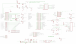 Main Board Version 2 Schematic
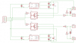 Gate Driver Schematic
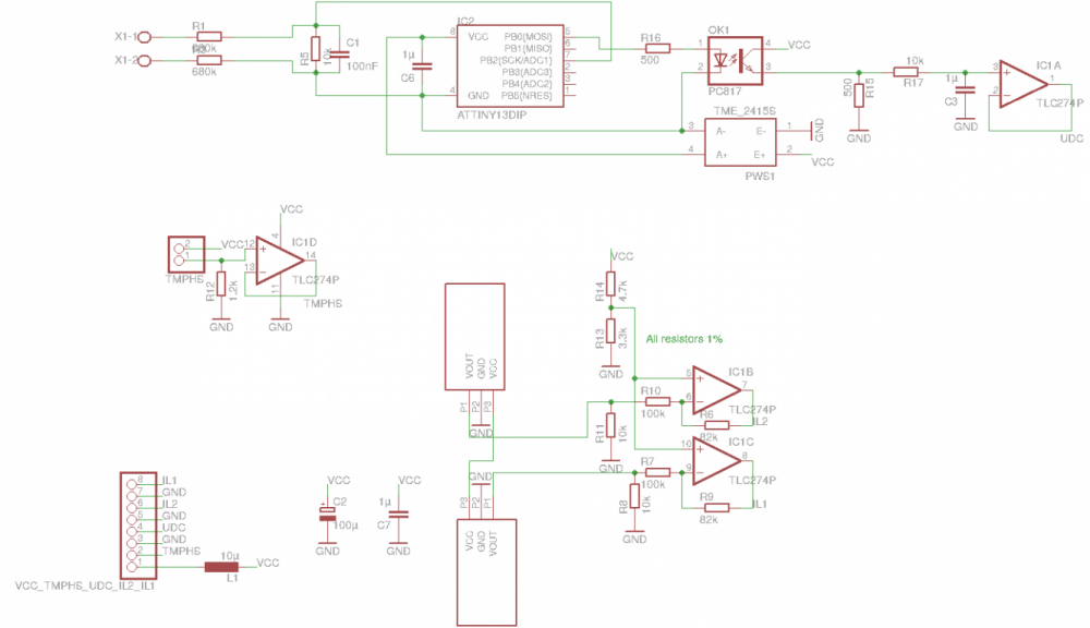
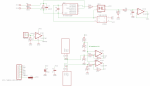 Sensor Board Version 3 Schematic
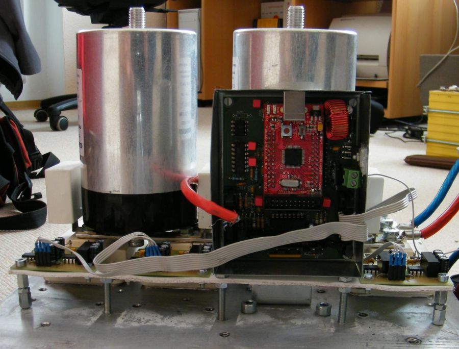
 Gate drivers connected with ribbon cable
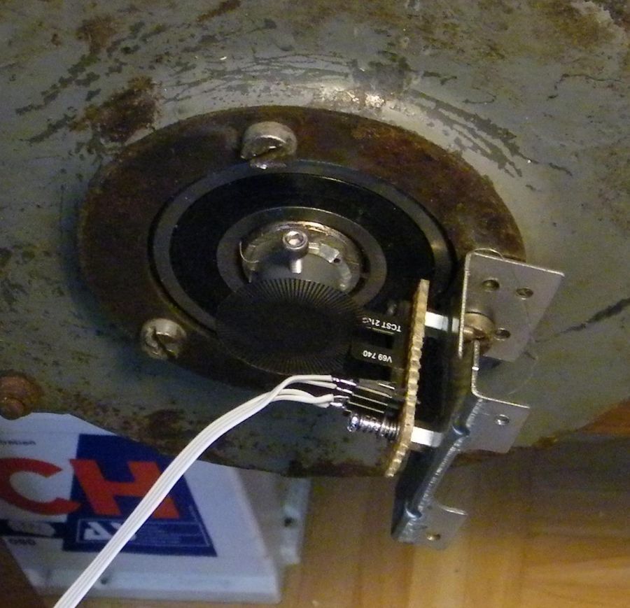
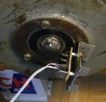 Example of speed sensor
 Ribbon Cable Usage
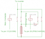 Precharge Arrangement


The controller board is split into two individual PCBs: the main board hosting the STM32 and the sensor board hosting the current sensors and some signal conditioning.
General instructions
New: Check out the assembly video.
The names of the individual parts are printed on the PCBs. The values are displayed in the schematic and the BOM. Assemble the PCBs accordingly. Whenever applying power, make sure to set a sane current limit as to not feed too much energy into a possible fault. Especially before inserting the STM32-H103 module make sure that the power supply is at the correct level (5V) and being fed to the correct pins. Test each PCB individually before connecting it to the system.
When populating the PCBs be advised that parts are VERY hard to remove in one piece unless you have a hot air gun. So make sure you insert them correctly especially parts that have a Pin 1 marking (all integrated circuits and resistor network RN2 on the main board).
The recent USBTTL cables have a 5V output. DO NOT connect it to the 3.3V input of the mainboard!
Errata
There are some glitches which can be easily fixed.
1. The socket for the external signals (JP5) has the pins mirrored. This causes the pins to show up on unexpected ribbon cables. Here is the map when looking from the top:
1 3 5 7  9 11 13 15 17 19 21 23
2 4 6 8 10 12 14 16 18 20 22 24
This results in the ribbon cable map:
2 1 4 3 6 5 8 7 10 9 12 11 14 13 16 15 18 17 20 19 22 21 24 23
2. A mistake happened when ordering the main board PCBs. Therefore the kit is shipped with a 26-pin header for JP5 but only has 24 holes. I have removed 2 pins from each header. Place it wisely to not take of the space of the main input cap. Insert only 24 cables into the corresponding socket.
3. The first batch of revision 3 sensor boards have a misleading silk screen for the DC/DC-converter "PWS1". Turn 180° to what the silk screen suggests. The "Pin-side" of the DC/DC must be facing the current sensors. Check the data sheet of in doubt and make sure the output side supplies the Attiny13 MCU.
4. It was recently discovered that the silkscreen of T1 on the mainboard is reversed. The circuit still works but the intention is to connect emitter to ground. Twist T1 by 180°.
For the recent kits errata 2-4 are irrelevant. I have left the twisted pin map of #1 in order to stay sort of compatible with version 1 boards.
First firmware installation
The STM32-H103 comes with a bootloader and a current software version. Both configuration and software updates use the UART which is accessible using the provided TTLUSB adapter. The on-board USB socket is unused! An update program is provided for linux 32-bit and 64-bit. To upgrade the software, extract the update program and the firmware image and type
./updater stm32_sine.bin /dev/ttyUSB0
If the binary doesn't work for you, there is also a python version
python updater.py -f stm32_sine.bin -d /dev/ttyUSB0
The update takes about 2s and when it is finished the green LED should flash
Using the web interface
Provided in the zip file is a web interface for configuring the inverter and monitoring values.
Edit config.inc.php and customize your serial device. Default is /dev/ttyUSB0.
Extract the files somewhere, then change to that directory and type
sudo php -Slocalhost:8000
Open your browser and type
localhost:8000
Thanks to forum member "dcb" for that one!
For a more permanent installation the script works just as well with apache+php.
Alternatively try this frontend. It is definitely more beautiful and even contains a BOM.
Connecting the sensor board
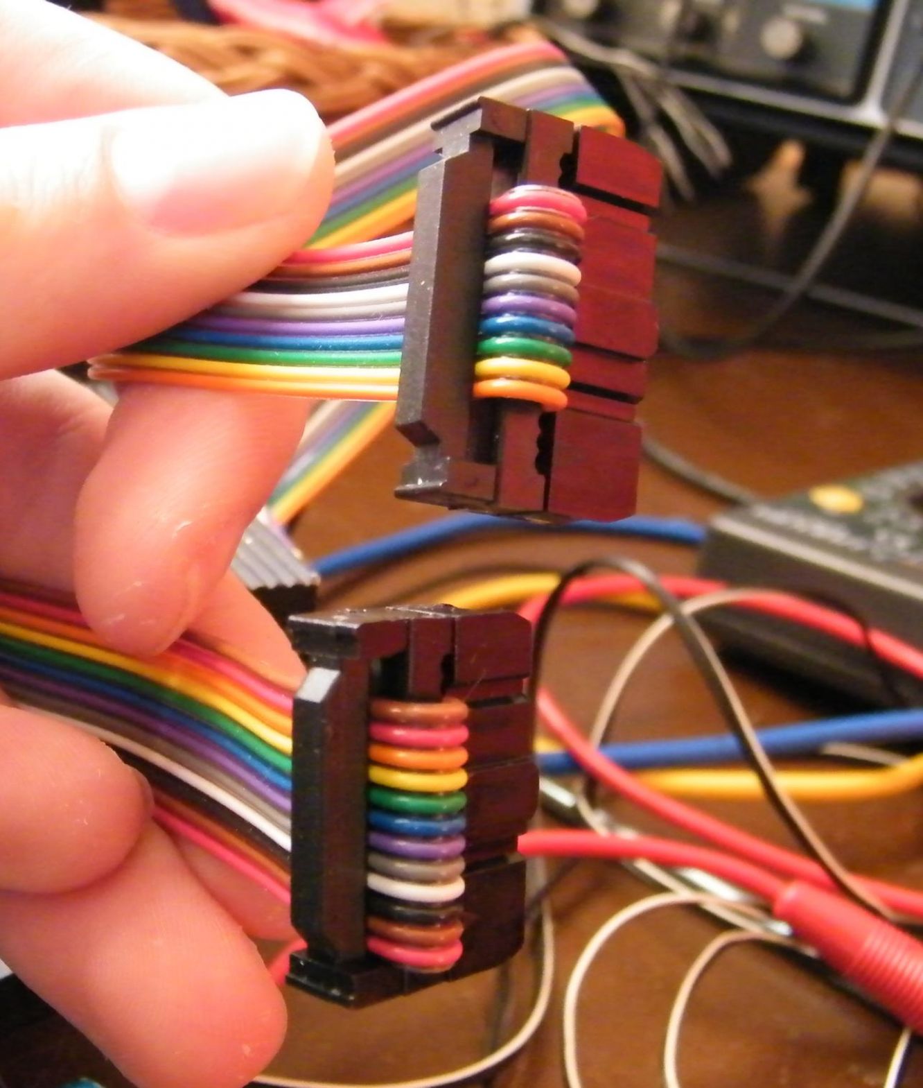
The sensor board can be connected with a shielded twisted pair cable for better noise immunity or a regular ribbon cable. The provided 10-pole ribbon cable must be inserted into the socket as shown. 3 slots must be blank on either side of the 16-pole socket. The shield connects to GND on both sides. Combine the pairs like this:
- pair: GND, IL1 (pin 7 and 8 on sensor board, 7 and 6 on main board)
- pair: GND, IL2 (pin 5 and 6 on sensor board, 10 and 9 on main board)
- pair: GND, UDC (pin 3 and 4 on sensor board, 5 and 4 on main board)
- pair: VCC, TMPHS (pin 1 and 2 on sensor board, 12 and 13 on main board)
Now verify the values by typing
get tmphs,il1,il2,udc
This command will display all 4 values. To repeat the command, simply type "!".
To calibrate the current, set il1gain and il2gain to 1. Then put a known current through the sensors by winding for example a 1.5mm² cable 10 times through both sensors. Then, using you lab power supply run 5A through your wound cable. Type:
get il1,il2
You will get something like
95.32
98.12
The gain factor is calculated by g=Ireading/(Iref*N) (Ireading: reply from get, Iref: reference current, e.g. 5A, N: number of turns through sensor, e.g. 10). So for our example il1gain=95.32/(5*10)=1.9064 and il2gain=98.12/(5*10)=1.9624. So type
set il1gain 1.91
set il2gain 1.96
save
Calibration is crucial to ensure correct operation of the over current limit!
Connecting the gate drivers
Connect the gate drivers with a ribbon cable like shown in the picture. Power up the inverter, which will now pull around 300mA @ 12V. If its less, one or more gate drivers are unpowered, if its more, there is an error on the drivers or the connection. Remove power quickly in that case. The inrush current is higher of course, so set the current limit of your power supply to about 1A.
When all is fine, connect pin 11, 13 and 17 to 12V as well to overcome the hardware PWM inhibit logic. Now type
start 2
This will start sine wave generation. Type
set fslipspnt 1
set ampnom 1
This outputs a clean 50/50 duty cycle on all 6 PWM outputs. Verify this with a scope on the main board, the gate driver inputs and the gate driver outputs. Also verify that there is about 1.5µs dead time between GTOP and GBOT.
Note that the sensor board has to stay connected at all times, otherwise the over current protection will kick in due to an implausible signal.
Connecting the IGBTs
Now you are ready for some more power. Connect the gate drivers to the IGBTs and repeat the steps above. The slope of the PWM will be less steep as to show that the gate driver is really working against the gates capacity. Connect a small voltage (like 30V) to the DC bus and verify that the PWM shows on the IGBT modules outputs and looks the same on all outputs. This circuit is completely symmetrical so the output should be symmectrical as well. If its not, there might be something wrong. There must be absolutely 0 current flow on the DC bus, otherwise you are experiencing shoot-through, i.e. the top and bottom IGBT of one leg are on at the same time. Correct this before continuing!
Connecting the motor
Now comes the big one. Connect a motor to the three output phases. Leave the DC voltage at a small value but make sure it can supply enough current (more than 10A). But also make sure to limit the possible current e.g. with a fuse. Now type
set fweak 10
start 2
set fslipspnt 10
set ampnom 100
This will start the inverter at 10Hz and the motor should spin at the corresponding speed.
Now type
stop
to stop the inverter. Connect the voltage that you actually want to run at to the DC input. Before turning on, you must configure the frequency/voltage curve. Therefor you have to do some math with your motors nameplate values. You need to calculate the frequency at which the motor can be driven with the maximum output voltage. Beyond that point, the motor operates in the field weakening region, therefor the parameter is called fweak. This calculates as follows:

So for a DC bus voltage of 350V, a nameplate frequency of 60Hz and a nameplace voltage of 200V you get fweak=60Hz x (350V/1.41)/200V = 74.5Hz. Now type
set fweak 74.5
start 2
set fslipspnt 10
set ampnom 100
The motor should spin as it did before but at its nomimal nameplate torque. You can try different frequencies. Should the motor only spin very shortly and stop, you might be hitting the current limit. It can be modified e.g. to 200A with
set ocurlim -200
If all is working save the current parameter set by typing
save
Alternatively you can use the python-script tuning.py to try and determine the parameters automatically. Start it in a linux console by typing
python tuning.py -d /dev/ttyUSB0
Connecting the speed sensor
This board has been designed with optical encoders in mind. So it supplies 30mA on pin 2 for an IR diode. Pin 3 expects an open collector pulse signal. The picture shows a very exposed version of such a sensor which explains the principle very well though. The controller needs to know how many pulses it gets per turn of the shaft. It also needs to know the number of pole pairs of your motor. You can deduce that from the nameplate or data sheet. Type
set numimp 64
set polepairs 2
start 2
The motor should now spin up smoothly.
Note that this controller only supports up to about 10000 pulses per second. So for example if you plan to spin your motor up to 10000 rpm which is 166.7 1/s the encoder mustn't generate more than 60 pulses per turn. The limit is imposed by the low pass filter and can be changed by populating a different resistor R3.
Some encoders require more than the provided 3.3V operating voltage. In that case try to "steal" 5V from the sensor board output. Alternatively you can leave out R2 and connect Pin 2 directly to 5V with a short wire.
Connecting the throttle pot
Now connect a pot to pins 1, 4 and 6. The slider goes on pin 6. Type
get pot
When the pot is at "full throttle" the value must be higher than if it is completely released. Write down the maximum and minimum value, add/subtract a bit of slack (like 10-20 digits) and tell the controller by typing
set potmin 2000
set potmax 3000
Now the pots position can be correctly translated to %. When completely released, you get -30% for regen (can be adjusted with parameter brknom), at full throttle you get close to 100% for acceleration. Verify by typing
get potnom
Some throttle assemblies offer 2 pots for redundance. In the current software version this is not supported but will be in upcoming releases. The analog input exists and can be connected.
If the pot value leaves the window defined by potmin and potmax the throttle command is set to 0.
Running slip control
Now start the controller in slip control mode by typing
start 1
As you reach 30% of throttle travel the motor should start spinning. The harder you press the more it will accelerate until it reaches its maximum speed (parameter fmax, preconfigured to 200Hz). When you let go the throttle the motor will brake to a standstill.
Once the whole setup is inside your car you can play with various parameters for fine tuning.
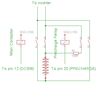
Connecting precharge and main contactor
Connect the precharge relay and the main contactor as depicted in the diagram. It is recommended to disconnect both battery poles. The inverter controls the two contactors by means of the DC bus voltage. When udc < udcsw then the precharge relay is closed, the main contactor is inhibited. When udc > udcsw the main contactor is closed as soon has the start signal (pin 7) goes high. The precharge relay is opened at the same time. udcsw should be set to about 80% of your nominal pack voltage. So if the latter is 360V set udcsw to 300V by typing
set udcsw 300
Connecting motor temperature sensor, emergency stop and motor protection switch
The software supports the KTY83 and KTY84 temperature sensor. Other types might be supported in upcoming releases. Note that the sensor has a polarity. When connected the wrong way it will saturate at 120°C. So even if the temperature rises above 120°C it will be displayed as 120°C. Connect it to pin 21 (negative) and pin 22 (positive).
Some motors have a protection switch that opens at some threshold temperature. You can connect it to 12V and pin 11. It will stop the inverter immediatly if tripped. If your motor does not have this feature, connect pin 11 to 12V.
The emergency stop serves a similar function. It can be installed in the drivers reach and will stop the inverter immediatly when 12V are interrupted (failsafe). Connect it to 12V and pin 17.
Forward and reverse
You can connect a 3-position switch for selecting the drive mode. Forward (pin 13) turns the motor in one direction, reverse (pin 15) in the other. If they are both low, no current is fed to the motor making this essentially the neutral position.
See Also
There are detailed pages for main board, sensor board and gate drivers.
Information about the softwares Parameters.
In-depth information can be found on the Hardware Principles and Software Principles page.
Forum Post about experimental parameter setup.