Theory of Operation
Hardware » Theory of Operation
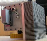 "Black box" view of the inverter
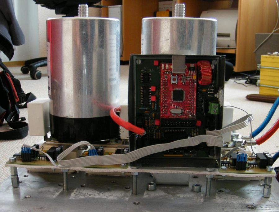
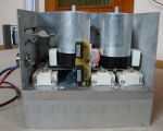 Inside view
 Controller
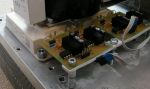 Gate driver
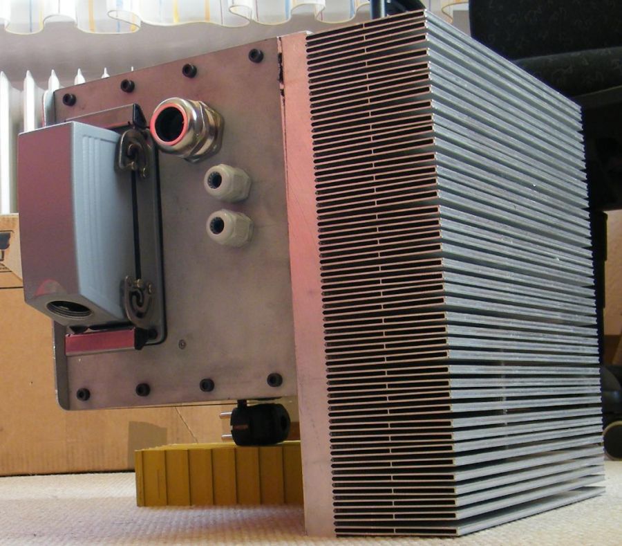
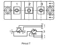
 IGBT half bridge module

In principle, an inverter is a rather simple device. The incoming DC voltage is distributed over 3 "bridges" each of which modulates the DC voltage to a sine wave with variable phase, amplitude and frequency.
Each bridge consists of 2 switches which can be controlled electronically. If the top switch is closed, the output is connected to high voltage, if the bottom switch is closed the output is connected to ground. If both switches are closed the inverter explodes. To set an average output voltage, the switches are toggled a couple of 1000 times per second. The ratio between top and bottom "closed-time" is called dutycycle. So say the incoming DC voltage is 500V. If the duty cycle is 0% the output voltage is 0V. If the duty cycle is 100% the output voltage is 500V. If the duty cycle is 50% the output voltage is 250V and so on.
If this principle is applied to all 3 bridges then 3 arbitrary voltages between 0 and 500V can be produced. The 3 inputs of the motor (commonly called L1, L2, L3) are connected to the 3 outputs of the inverter. So the motor only "sees" the voltage difference between the outputs. If all 3 operate at the same duty cycle the motor sees 0V. If bridge one produces 300V, bridge 2 produces 200V and bridge 3 produces 250V then the motor sees -100V between L1 and L2, 50V between L2 and L3, and -50V between L3 and L1. Depending on the specifics of the motor according currents flow.
When building an inverter some nasty details show up. Lets go over them.
The DC bus
When I started out building my first inverter I thought "lets ditch those stupid capacitors, the batteries are capacity enough". Not so, theres a reason for this expensive parts. Let me explain with some water. Say you're watering your garden with a hose that has some spraying device on the end which allows you to interrupt the water flow. If you interrupt the flow the hose will rock a bit. Thats because the water somewhere back in the pipe doesn't "know" that you've just closed the valve. So for a short moment the water will keep coming and the pressure inside the hose rises. The longer the hose, the stronger that effect- The same happens when interrupting an electric current flow. You interrupt, the current keeps coming and thus the voltage rises. The switches only withstand a finite voltage. The ones I use are specified for 1200V. With the cable length used in a car the voltage will easily rise above 1200V when switched off and the switch breaks.
To cure this problem the excess current needs to be trapped somewhere. It it must be trapped as close to the switch as possible because any remaining distance is another piece of "hose". Thats what the big round and small cubic capacitors are for. The round ones can take a lot of excess current while the small ones catch the remaing current right at the switches terminal. The closer your DC voltage comes to the breakdown voltage of the switch the more care must be taken to catch the excess current. With a lot of effort you can operate 1200V switches at around 900V. With less effort you can operate them at 700V. So to keep stuff simple the switches need to be oversized.
Gate drivers
The switches are controlled with a small voltage of typically 15V. At 0V the switch is off, at 15V it's on. Keeping the switch on or off is easy. But changing state is rather hard. Just like switching on the light in your kitchen requires some mechanical force. The electric current needed to operate our switches is 2.5A. More serious power electronics even require 40A. So gate drivers for power electronics are power electronics.
Another challenge is on the high side, i.e. the switch thats connects the output to the high voltage. I stated above that 15V are needed to switch on. 15V in respect to what? In respect to the source i.e. the output of the high side switch. So as the high side is switched on, its output rises to the high voltage. So the control voltage has to rise with it. Imagine a lift that rises while you push a button inside it. You better be standing inside the lift as you push the button.
This last aspect presents the third function of a simple gate driver: galvanic isolation. It's like a guy standing in the lift operating it for you. No matter where he is, you can stay where you are. In an inverter thats also a safety issue. You don't want your controller side to be electrically connected to the power side.
More advanced gate drivers take care that bottom and top switch are never closed at the same time and they insert a security margin (called deadtime) between opening one switch and closing the other. They also monitor the voltage over the switch as the switch is closed. If it rises to high then the switch is overloaded and will be opened. This is called desaturation detection or short desat. The deadtime can be replicated in software, the desat can be (almost) replaced with fast current monitoring.
Step by Step
I'm often sent emails with ebay links to all sorts of IGBT modules. And often they are unusable. What you want is an IGBT half bridge module as depicted above. It is two IGBTs and two diodes in one case.
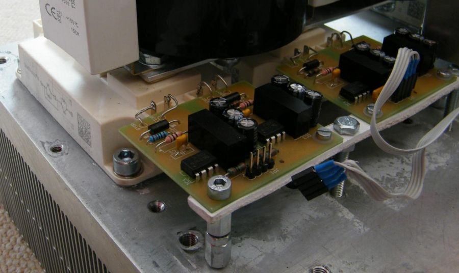
Next up is capacitor selection. It's hard to give general advise. I always advise against elcaps because of their low ripple current rating. Better use film caps as shown above. If you can get your hands on any cheap and large (meaning above 300µF for filmcaps or 3000µF for elcaps) caps then give it a shot. Watch the DC bus voltage with a scope while running the inverter at load. You don't want to see excessive ringing or spikes. Here are some examples of what you do and don't want to see.
In the power stage depicted above I used 1.5µF snubber caps on each IGBT terminal plus two 420µF film caps. All components have screw terminals with the same width. That makes handling very easy. Everything is bolted onto a pair of alloy strips forming a simple low inductance DC bus.
To suppress high frequency common mode signals you can place a ferrite core around the DC bus or the DC cables. This will give you a better chance to pass EMC compliance tests.
Last but not least place the gate drivers directly onto the corresponding pins of the module. The PCB has been designed to line up. Make use of that. 1cm of wire should be enough!
With the setup depicted above I passed the ECE-R10 EMC compliance test with a good margin. It's not that hard.