Gate Driver
Hardware » Gate Driver
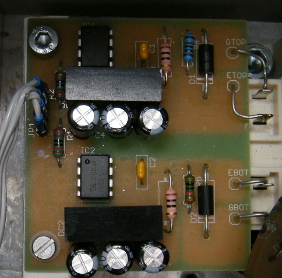

The gate drivers convert the logic level PWM signals to a bipolar signal that can be used to drive the gate of power semiconductors. They also isolate the power section from the control section.
DC/DC converter
To provide power to the power section (the secondary side) isolated DC/DC converters are used. They provide a continues power of 1W. This power limits the PWM switching speed. The input voltage to the converters is 5V and their output voltages are -9V and +15V. (Used to be -15).
The formular is P=Ug²/Rg*(tr+tf)*fPWM with Ug=24V, Rg=4.7Ohms.
Example. tr=50ns, tf=110ns, fPWM=8.8kHz (SKM400GB126)
-> P=24²/4.7*(50ns+110ns)*8800Hz = 0.17W.
Please note, that this formular is an approximation. In the datasheet, together with the tr/tf times a gate resistor is stated in the conditions. If this gate resistor is less then 4.7Ohm of this driver this means that tr and tf will be a bit higher as well. If in doubt, please measure tr and tf with a scope.
Gate Drive Optocouplers
To transmit the logic level signals to the secondary side, Si8261 gate drive isolaters are used. They provide a peak drive current of 4A.