Main Board Version 1
Hardware » Main Board Version 1
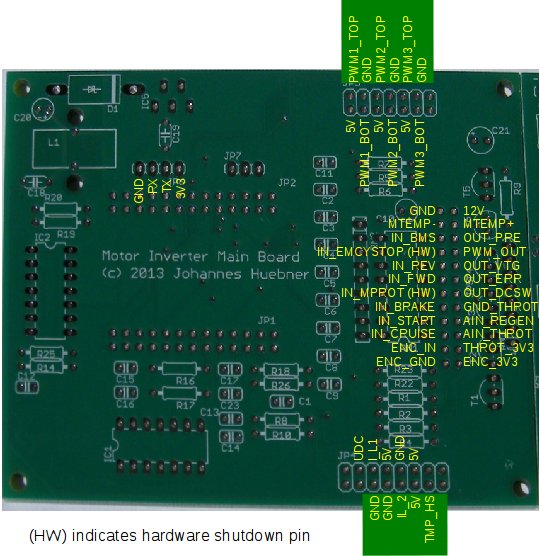
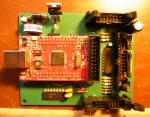 Main board
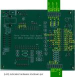 Mainboard connections
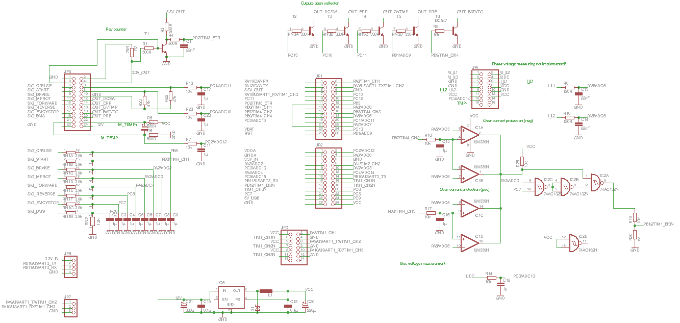
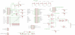 Schematics
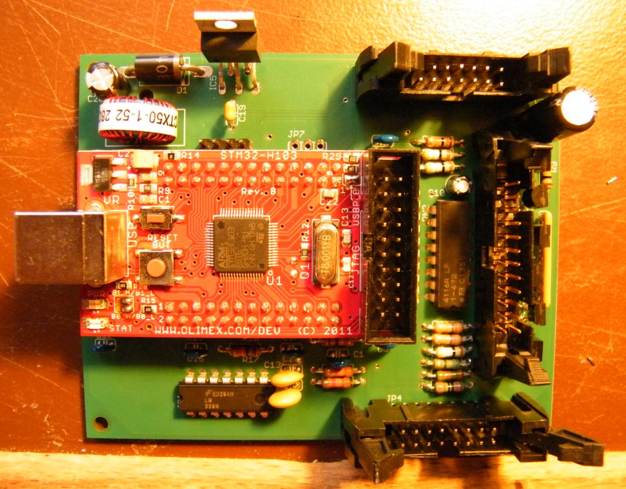
The main board is the heart of the inverter system. It contains all the intelligence that is needed to convert the users inputs into motor shaft movement. It also contains all the protection circuitry to avoid damage in case of errornous inputs.
Its distinct features are:
Digital inputs
There are external 8 digital inputs on JP5. A voltage of >7V is interpreted as a logical 1 (high). They all have a cutoff frequency of 40Hz.
- Cruise Control (Pin 5).
This input sets the current motor speed as the set point for cruise control. Cruise control is disabled with the Brake input. - Start (Pin 7).
This input starts the inverter operation. - Brake input (Pin 9).
This input is connected to the brake pedal. It sets a configurable negative torque (regen) which overrides the throttle. I.e. if you press both, brake pedal and throttle, the throttle is ignored. - Motor Protection switch (Pin 11).
This input is connected to the thermal protection switch that is embedded into many motors. Its function is to inhibit the PWM signals when the motor overheats. This input directly controls the PWM signals without software interaction. The PWM is enabled as long as this input is high and shut down as soon as it goes low. If your motor does not have such a switch, tie the input high permanently.
Of course you can use this input for any other fault condition, e.g. the error signal of a 3rd party gate driver. - Forward (Pin 13).
If this input is high the motor spins forward. - Reverse (Pin 15).
If this input is high the motor spins backward. When neither input is high the motor will not spin at all. - Emergency Stop (Pin 17).
This input has the same function as the motor protection input. It can be used for an emergency stop button. Tie it high otherwise. - BMS input (Pin 19).
This input limits the motor torque (both negative and positive) if a BMS signals an over or undervoltage condition. It is active high, i.e. high means over/undervoltage.
Digital outputs
There are 4 external open collector outputs on JP5. They sink up to 2A.
- DC contactor output (Pin12)
This output is activated when the bus voltage is above a given threshold and the start pin goes high. It is disabled on overcurrent, motor overheat and emergency stop. - Error output (Pin 14)
This output is activated on over current, motor overheat, emergency stop, throttle out of range. - Voltage output (Pin 16)
This output is activated when the bus voltage surpasses an upper or lower threshold. - Precharge output (Pin 20)
This output is activated when the inverter is powered up. It is disabled as soon as the DC contactor is enabled.
PWM outputs
There is one external PWM output on JP5, Pin 18. It outputs a duty cycle that is proportional to the motor temperature. Its offset and gain is software configurable. The frequency is fixed to 17kHz. It is an open collector output so it can be used with most temperature gauges in cars. It can sink up to 100mA.
There are 6 internal PWM outputs on JP3. Pins 4, 8 and 12 provide a GND connection, Pins 1, 5 and 9 provide 5V. The outputs are 3.3V, 16mA.
- PWM Top phase 1 (Pin 2)
- PWM Bottom phase 1 (Pin 3)
- PWM Top phase 2 (Pin 6)
- PWM Bottom phase 2 (Pin 7)
- PWM Top phase 3 (Pin 10)
- PWM Bottom phase 3 (Pin 11)
There is a configurable dead time between top and bottom outputs.
Analog Inputs and over-current protection
There are 3 external analog inputs on JP5. The reference voltages are provided as well (Pin 4) so the inputs are connected to sensors or pots directly.
- Throttle input, 0-3.3V (Pin 6).
Cutoff frequency 16Hz, input resistance 47k. - Regen pot input, 0-3.3V (Pin 8).
Cutoff frequency 16Hz, input resistance 47k. - KTY83 temperature sensor input (Pin 22 positive, Pin 21 negative).
Cutoff frequency 16Hz
There are 4 internal analog inputs on JP4. Pins 5,7 and 10 provide a GND connection, Pin 8,11 and 12 provide stablelized 5V.
- Udc (Pin 4)
Bus voltage input. 0-3.3V, cutoff frequency 16Hz - Il1 (Pin 6)
Current phase 1. 0V=-Imax, 1.67V=0A, 3.3V=Imax (software configurable). Cutoff frequency 48kHz. - Il2 (Pin 9)
- Heatsink temperature (Pin 13)
The two current sensors are used for the programmable hardware over-current protection. A trip limit can be programmed that configures a hardware comparator. When the given current limit is hit, the PWM signals will be shut down without software interaction.
Encoder Input
There is an input for a pulse encoder on JP5. Pin 3 can be connected to an open collector output of an encoder. Its input resistance is 500 Ohms. The cutoff frequency is 6kHz. E.g. a 60 pulses/rotation encoder can spin up to 6000 rpm before the limit is hit. By changing the value of R3 the cutoff frequency can be varied (lower value, higher frequency).
Pin 2 provides 3.3V with an output resistance of 75 Ohms to power the diode of an optical encoder with 30mA.
Communication
JP6 provides a TTL level (3.3V) UART interface. It can be directly connected to the provided TTLUSB adapter. Pin 1 provides the 3.3V net of the Olimex board. It can be used to power the board or to power an external module like a ZigBee transceiver. 100mA should not be exceeded. Pin 2 is TX, Pin 3 is RX and Pin 4 (next to the inductor) is GND.
The communication parameters are fixed to 115200 8N2 (2 stop bits!).
Power input
The main board contains a regulated buck converter to power all of its components. The allowed input voltage is 7-26V.
Pin Header Summary
Pin Header JP5
| Pin | Name |
| 1 | GND |
| 2 | 30mA output for IR diode |
| 3 | Encoder input |
| 4 | 3.3V |
| 5 | Cruise Control Input (12V) |
| 6 | Throttle Input (0-3.3V) |
| 7 | Start input (12V) |
| 8 | Regen Pot Input (0-3.3V) |
| 9 | Brake Input (12V) |
| 10 | GND |
| 11 | Motor Protection Switch (12V, PWM inhibit when low) |
| 12 | DC contactor output (open collector 3A) |
| 13 | Forward (12V) |
| 14 | Error Signal (open collector 3A) |
| 15 | Reverse (12V) |
| 16 | Over/Under Voltage (open collector 3A) |
| 17 | Emergency Stop (12V, PWM inhibit when low) |
| 18 | Temperature PWM output (open collector 100mA) |
| 19 | BMS Over/Under Voltage input (12V) |
| 20 | Precharge Output (open collector 2A) |
| 21 | Motor Temperature Input - |
| 22 | Motor Temperature Input + |
| 23 | GND |
| 24 | Vcc (7-26V) |