Hardware
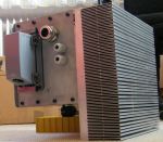
The inverter consists of three distinct electronic circuit boards, power electronics, heatsink and a waterproof case. On the following pages the theory of operation and the circuit boards are discussed.
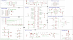
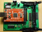
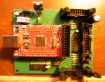
Main Board Version 3
Main Board Version 2
The version 2 mainboard is almost pin-compatible with the version 1 main board. It adds CAN communication, support for quadrature encoders, desat signalling support and many other feature improvements.
Main Board Version 1
The main board is the heart of the inverter system. It contains all the intelligence that is needed to convert the users inputs into motor shaft movement.
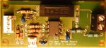
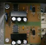
Sense Boards
The sense boards provide the inverter with values for the DC link voltage, heat sink temperature and two phase currents.
Gate Driver
The gate drivers convert the logic level PWM signals to a bipolar signal that can be used to drive the gate of power semiconductors. They also isolate the power section from the control section.
Theory of Operation
In principle, an inverter is a rather simple device. The incoming DC voltage is distributed over 3 "bridges" each of which modulates the DC voltage to a sine wave with variable phase, amplitude and frequency. Read here about the details.