BMW I3 Fast Charging LIM Module
The BMW LIM module is a CCS, CHAdeMO and AC charging controller. It is used to communicate between the vehicle and the public charging infrastructure, to allow fast charging to occur.
As these can be found affordably on eBay and from auto wreckers, they have been pursued as an open-source charger-interface project.
The LIM is also available new from BMW spare parts suppliers for € 240. If you get it new, it comes without firmware loaded, and it must be programmed first.
External links
github.com/damienmaguire/BMW-i3-CCS
> CAN logs
> STM32 ZombieVerter VCU software
Design Guide for Combined Charging System (2015)
EV Charging Definitions, Modes, Levels, Communication Protocols and Applied Standards
Connectors and Pinouts
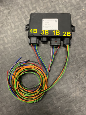
All connectors are available at https://www.auto-click.co.uk/ worldwide.
| Label | Description | Compatible Plugs |
|---|---|---|
| 4B | 12 Pin Connector | BMW 61138373632
Audi 4E0 972 713 TE 1534152-1[1] / 1534151-1 |
| 3B | 8 Pin Connector (CHAdeMO models only) | BMW 61138364624
Audi 4F0 972 708 TE 1-1534229-1 |
| 1B | 16 Pin Connector | (?Hirschmann 805-587-545?)[2]Auto-Click UK Part link has Pin 13 through 16 blocked. Received a Mercedes Part from them instead of BMW using this part number. Please check the part for proper compatibility |
| 2B | 6 Pin Connector | BMW 61138383300
Audi 7M0 973 119 |
| X | Replacement Pins | 5-962885-1[5] |
| X | Rubber Seal | 1-967067-1[6] |
| X | (for the connector on the i3's Charge Port Cable Lock, |

| Pin # | Function | Description |
|---|---|---|
| 1B-1 | LED_S | Charge Port Lighting (not necessary) |
| 1B-2 | - | |
| 1B-3 | LED_M | Charge Port Lighting (not necessary) |
| 1B-4 | LOCK_MOT+ | Charge Port cable Lock Motor |
| 1B-5 | LOCK_MOT- | Charge Port cable Lock Motor, and reference for 1B-16. |
| 1B-6 | CAN_H | Powertrain CAN |
| 1B-7 | CAN_L | Powertrain CAN |
| 1B-8 | IGN | Wake up signal input and output +12V (ignition, contact 15) |
| 1B-9 | VCC | Constant Power +12V |
| 1B-10 | GND | Ground |
| 1B-11 | - | |
| 1B-12 | - | |
| 1B-13 | - | |
| 1B-14 | - | |
| 1B-15 | CHARGE_E | Goes to KLE. Guessing this is charge enable or drive interlock signal? (Not necessary) |
| 1B-16 | LOCK_FB | Charge Port cable Lock Feedback (1k unlocked, 11k locked), referenced to 1B-5[7]. |
| Pin # | Function | Description (BMW) | Description (MINI)[8] |
|---|---|---|---|
| 2B-1 | CP | Pilot (charge port) ~620 ohms to GND is needed if no original i3 charge port is used! | Pilot (charge port) |
| 2B-2 | PP | Proximity (charge port) | Proximity (charge port) |
| 2B-3 | Jumper | Connected to Pin 4 | PE / GND |
| 2B-4 | Jumper | Connected to Pin 3 | Connected to Pin 5 |
| 2B-5 | PE / GND | Ground (charge port earth) | Connected to Pin 4 |
| 2B-6 | - | US CCS1 version connected to 2B-2 | N/C (TBD if used for US CCS1) |
3B Pinout:
- N/A (for CHAdeMO only)
| Pin # | Function | Description |
|---|---|---|
| 4B-1 | POS_CONT+ | Positive HV Contactor Control (Contactor coil resistance must be ~15 ohms) |
| 4B-2 | NEG_CONT+ | Negative HV Contactor Control (Contactor coil resistance must be ~15 ohms) |
| 4B-3 | POS_CONT- | Positive HV Contactor Control (Contactor coil resistance must be ~15 ohms) |
| 4B-4 | NEG_CONT- | Negative HV Contactor Control (Contactor coil resistance must be ~15 ohms) |
| 4B-5 | U_HV_DC | Charge Port DC Voltage (current input 3-20mA?)(1.42V for 0V HV, linear to 4.8V for 500V HV)[9] |
| 4B-6 | LED_RT | Red charge Status Light (12V RGB LED) |
| 4B-7 | LED_GN | Green charge Status Light (12V RGB LED) |
| 4B-8 | LED_BL | Blue charge Status Light (12V RGB LED) |
| 4B-9 | LED_GND | Charge Status Light Ground (common cathode of RGB LED) |
| 4B-10 | COV_MOT- | Charge Port Cover Motor (Not necessary) |
| 4B-11 | COV_MOT+ | Charge Port Cover Motor (Not necessary) |
| 4B-12 | COV_FB | Charge Port Cover Feedback (connect to GND to simulate open cover[10])(To be left floating for contactors weld test) |
Wiring Diagram

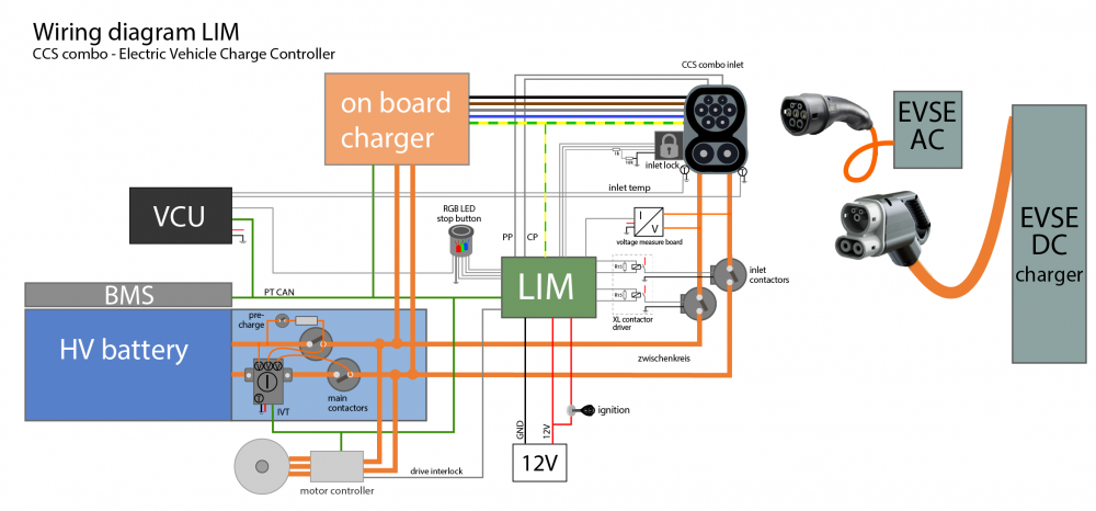
Note [18Jun2022 ALS]: In the above diagram, some details may be non-current, eg the Charge Port Cover sensor is not shown, but its line @ 4B-12 must be floating (signalling that the Charge Port Cover is closed (?)) in order for the LIM to proceed with its welded contact tests; 4B-12 is tied to Ground (?) to indicate that the cover is open[11].
Wiring notes
Make sure you mount the LIM as close to the charge socket as possible and keep the pilot wire separate from the high power wiring.
Bad pilot wiring can result in SLAC, PLC, or other communication problems.
Additional components for a LIM installation
Isolated DC charge inlet voltage sense board
The LIM gets the inlet DC voltage from a board in the KLE.
This board needs to produce an isolated 3-20mA current signal (or: 1.42V for 0V HV, linear to 4.8V for 500V HV)[12] from the high voltage DC voltage.
A circuit of a voltage sense board is shared here and can be purchased here.
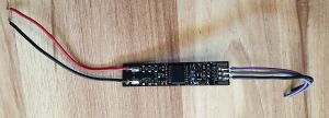
An alternative voltage sense board is available here.

Fast charge contactor
The LIM produces a 12V, 50% PWM on the positive and negative fast charging contactor outputs and measures the current draw of the contactors.
The BMW OEM fast charge contactor relays, located in the KLE, are (2) TE EVC135 RELAY, SPST-NO, DM (# 2138011-1).
https://www.te.com/usa-en/product-2138011-1.html
Similar, though not exact, replacements are available from EVcreate
Larger contactor control
If you want to use larger contactors with PWM economizer or dual coil, use small relays to drive them and place a 15 ohm resistor (with heat sink) in parallel with each to simulate the original contactor coil's impedance.
Each of the two 15 ohm resistors must dissipate ~6W @ 13.4V, 50% PWM.
Further investigation is needed to find out if the LIM also detects a contactor failure via the current draw.

Charge port

SAE J1772 (US) and IEC 61851 (international) cover the general physical, electrical, communication protocol, and performance requirements for the electric vehicle conductive charge system and coupler.
https://en.wikipedia.org/wiki/SAE_J1772#Signaling
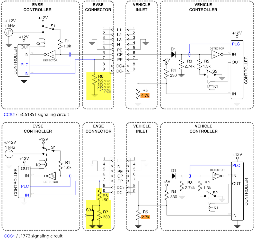
The original BMW i3 Type 1 charge port has 2.7 kΩ between PP and PE and no connection between CP and PE, as J1772 describes.
The Type 2 charge port used in Europe probably has 4.7 kΩ between PP and PE. (from Phoenix datasheet. Not confirmed!)
Make sure to match these if you want to use a different charge port. Some brands use different resistance values.
The CP communication is similar for US Type 1 (1-phase) and EU Type 2 (3-phase) charge ports, but the PP circuit is different.
Charge port lock
In the BMW i3 a quite expensive Phoenix/Delphi CCS charge port is used, and it would be convenient to be able to use the cheaper Duosida CCS charge ports.
The charge port lock should work with the Duosida lock as well but the feedback (1k unlocked, 11k locked) is a bit different which requires some additional resistors.
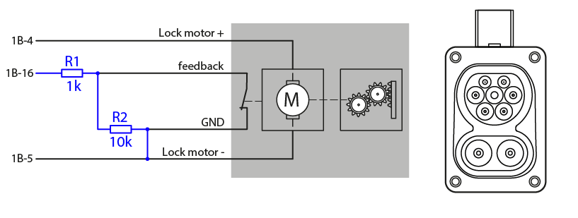
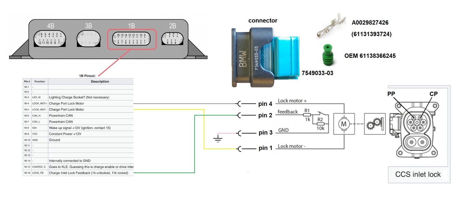
If using an OEM BMW i3 CCS charge port, the Kuster cable lock uses these connector parts:
- Connector shell: BMW 12527549033[13] or Hirschmann 805122541[14]
- Terminals: BMW 61131393724
- Terminal seals: BMW 61138366245
Locks in other charge ports
- Peugeot: 2 motor pins, 2 feedback pins. Feedback is some sort of 2 pin semiconductor device, maybe hall effect. Feed 12V via 1k resistor, outputs about 10V when locked, 3V when open. A solution is needed for converting this to the LIM.
RGB charge indication light
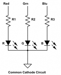
The RGB charge indicator LED should have a common cathode and series resistors for 12V DC.
Nice push buttons with an integrated RGB LED are available on Aliexpress for a few dollars.
The switch signal is useful to stop charging and has to be connected to the ECU. The ECU then terminates the charging process over the CAN bus.
Wake/sleep
The LIM will wake up under any of these circumstances:
- When 12V is applied to the hardware wake up line (1B-8).
- On plug insertion.
- On opening of the charge port door.
- When the LIM sees CAN message 0x12F.
The hardware wake up line works in both directions. I.e., the LIM can be woken by 12V on the hardware wake up line, but, similarly, when the LIM wakes up it will put 12V on the wake up line itself. This can be used to do things like waking up an OBC on plug insertion.
Programming a new LIM
If you purchase a new LIM, there is no configuration loaded; it is "virgin", and must be configured before use.
There are at least two ways to program a virgin BMW i3 LIM:
- Use BMW E-Sys software in combination with a salvaged Body Domain Controller, and possibly requiring a matching physical key[15];
- Use a Vector CAN (or similar) and a Fahrzeugauftrag (FA) file to edit and write information to the LIM without E-Sys[16]
Programming LIM using E-Sys and a BDC/Key
Damien managed to program a brand new LIM with a i3 BDC (Body Domain Controller).
He caught a CAN log of the programming session: https://github.com/damienmaguire/BMW-i3-CCS/tree/main/Programming/Logs
Hopefully we figure out how to do it with a few CAN messages. In the meantime, Damien is offering LIM programming as a service: https://www.evbmw.com/index.php/evbmw-webshop/evbmw-serv/limprg.
Basic shopping list if you want to program a LIM:
- Software:
- Esys 3.36 from here: https://disk.yandex.ru/d/3XLfVVYHFq8qQw
- pszdata lite from here: https://disk.yandex.ru/d/Y0w0r5T1ElMVdA
- Hardware:
- BMW LIM (see "LIM hardware" section below), connectors and pins (see "Connectors and Pinouts" section above).
- BMW i3 BDC (Body Domain Controller): basically the main ecu in the i3 that gates all the data around the car.
- Damien sourced his from: https://www.evbreakers.com/ noting They even threw in the plugs and few cm of harness for free.
- According to realoem.com, the first BDC (used in 2014) was p/n 61359354010
- A fuller list of the various BDCs over the subsequent years can be found here here:https://www.realoem.com/bmw/enUS/partxref?q=61359354010. Thankfully, there is a very wide retro/cross-compatibility
- Also found some part numbers in ebay listings not seen in the realoem list (maybe a North America vs EU thing?):
- 61-35-8-715-974, 61-35-5-A40-2F9
- Car key from the same car as the BDC. EDIT: this may not be necessary as the BDC can be put into "on" mode by running the full fault delete function using ISTA [17]
- Wondering if a non-matching used or new fob could be used/reprogrammed if the BDC donor's VIN was known?
- BDC simulator: https://www.aliexpress.com/item/1005002317110375.html
- Enet cable: https://bcables.com/
- USB to Ethernet adapter if your PC / laptop does not have a spare Ethernet port.
- Two extra pins for Conn8 on the BDC to bring out PT CAN.
- DC power supply or 12v battery.
Programming LIM using Vector CAN and Fahrzeugauftrag (FA) file
- Hardware requirement: TBD
- Vector CAN (can other hardware be used?)
- Software requirement: BMW E-sys v3.34 (tested[18])
- Advantages/Disadvantages
Charge control
The EVSE (charging station) shares its charging capacity limits via PWM during IEC 61851/ J1772 AC charging, or via PLC during DIN 70121 or ISO 15118 CCS sessions, but often the car cannot handle the max available power of the charging station.
The actual battery voltage and battery current values are needed by the LIM to check the response of the charging station. In this setup, the battery voltage and current are measured by an Isabellenhütte IVT CAN bus sensor, but these values could also be measured and shared on the CAN bus by the BMS. (CAN message 0x112)
Contactor Test
This is required before the LIM will proceed past the Precharge state during ccs charging.
To get it to do a contactor test following procedure has been determined
For LIMs 61 35 6 828 052 and later (to be confirmed)
- HV battery voltage to be present at vehicle side of contactors
- Charge Port door state closed (charge door feedback pin 4B-12 floating)
- charge door feedback is set to locked in 0x272 byte 2
- Charge Port Voltage Sense feedback with contactors open needs to be above 60V
- Fault set in 0x272 byte 2
- Ignition in 0x12F byte 2 needs to toggle from OFF 0x88 to ON 0x8a
- LIM will cycle contactors during weld test and clear fault in 0x272 byte 2
For LIMs before 61 35 6 828 052 (to be confirmed)
- HV battery voltage to be present at vehicle side of contactors
- Charge Port door state is closed, feedback in 0x272 byte 2
- 12V permanent to be connected to the LIM
- Ignition in 0x12F byte 2 needs be ON 0x8a
- LIM will cycle contactors during weld test and clear fault in 0x272 byte 2
celeron55's notes
Some detail of a tested 61 35 6 828 052 unit that may or may not be of interest to anyone:
- The intention is to make the LIM do this test at vehicle power up. In Zombie terms that means when going into the MOD_RUN state.
- The LIM will do the contactor test if it sees for a duration of 3 seconds that:
- The charge door is closed according to feedback (feedback line at 12V). 0x272 byte 2 bits 0 and 1. On Zombie that's the CP_DOOR parameter.
- The inlet voltage sensor is giving a low enough value (the limit is 60V according to above). 0x3B4 byte 7. On Zombie that's the CCS_V_Con parameter.
- The CAN ignition bit in 0x12F byte 2 was OFF earlier. (0x8a=ON, 0x86=OFF)
- The CAN ignition bit in 0x12F byte 2 is ON currently. On Zombie this gets set when opmode==MOD_RUN. Charging is disabled in opmode==MOD_RUN, so afterwards before charging it needs to be changed yet again to another value.
- What happens in the contactor test is that the LIM closes the contactors for a bit and then opens them. If the LIM likes what it sees, this clears the 0x272 byte 2 contactor bits to 0. On Zombie that's the CCS_Contactor parameter.
- On the bench, the LIM doesn't seem to care if the inlet voltage sensor doesn't sense a voltage during the test. However on the bench it was impossible to tell whether it would actually proceed to charge or not.
- The meaning of the CCS_Contactor values are as follows. Values other than 0 and !=0 may not be visible in UIs, but due to the nature of how the value is read from CAN, it can have other values than 0 and 1.
- 0 = Open
- 1 = Closed (Assuming)
- 8 = Doing contactor test
- 24 = Inlet voltage high / udc low
- 28 = Waiting for ignition cycle
Battery-dependent charging current control
During (fast) charging a cell voltage and cell temperature dependent current limit is very important.
The BMS or VCU should limit this value according to the battery specifications and protect the cells from damage and ageing at all times.
(Not yet implemented to the STM32 / ZombieVerter VCU project)
CCS inlet temperature sensors
Many CCS charge ports have DC and AC contact temperature sensors to avoid overheating if the contact resistance is high for some reason. The BMW's LIM has no temperature sensor inputs, but the VCU/charge controller could be connected to these sensors (usually PT1000 or NTC) and charging current could be reduced if the inlet gets too hot. (Not yet implemented to the STM32 / ZombieVerter VCU project)
However, this temperature measurement is also done on the charger side, on the CCS cable itself. Chargers will protect themselves from overheating the CCS pins.The absolute max pin temperature allowed can range from 70-90*C depending on quickcharger brand.
AC charging (on board charger control)
The LIM also handles the (lower level J1772 / IEC61851) communication during AC charging and shares measured PP (charging cable) and CP (charging station) AC current limits in the CAN message 0x3B4 EVSE info.
It is not possible to have two car-side charge controllers connected to the pilot line simultaneously. It is recommended to control the charger by CAN bus. If your charger needs the pilot signal, you will have to emulate it or switch the pilot connection wiring over to the active charger during AC charging.
If the onboard charger accepts an AC current limit, this value can be directly used but some chargers can only be controlled with DC current commands.
Because we don't know the actual AC current, we can only estimate it with a fixed AC voltage and charger efficiency.
DC_current = fixed_AC_voltage * CP_PP_current_limit * phase_count * charger_efficiency / DC_voltage
CAN communication
A DBC CAN database file can be found here: I3 LIM CAN dbc1
This list has to be cleaned up once we know which messages are actually necessary for the LIM.
| ID | Function | sent by | interval | Notes |
|---|---|---|---|---|
| 0x112 | BMS msg. | VCU or BMS | 10ms | needed |
| 0x12F | Wake up | VCU | 100ms | needed |
| 0x3E9 | Main LIM control | VCU | 200ms | needed |
| 0x2F1 | Lim DC charge command 2. | VCU | 100ms | needed |
| 0x2FA | Lim DC charge command 3. | VCU | 80ms...1s | needed (low interval during CCS start up) |
| 0x2FC | Charge flap control | VCU | 100ms (4s) | needed (constant values work) |
| 0x431 | Battery info | VCU | 200ms | needed but does not control anything |
| 0x432 | BMS SoC | VCU or BMS | 200ms | display SoC needed |
| 0x03C | Vehicle status | VCU | 200ms | (constant values) |
| 0x1A1 | Vehicle speed | VCU | 20ms | (constant values) |
| 0x2A0 | Central locking | VCU | 200ms (4s) | (constant values) |
| 0x3F9 | Engine info | VCU | 1000ms | (constant values) |
| 0x3A0 | Vehicle condition | VCU | 200ms | (constant values) |
| 0x51A | Network management | VCU | 200ms | (constant values) needed? |
| 0x540 | Network management 2 | VCU | 200ms | (constant values) needed? |
| 0x510 | Network management zgw | VCU | 200ms | (constant values) needed? |
| 0x328 | Counter | VCU | 1s | needed |
| 0x3E8 | OBD reset | VCU | 1s | (constant values) |
| Messages sent by LIM | ||||
| 0x29E | CCS charger specs | LIM | ||
| 0x2EF | Min. available voltage from the CCS charger. | LIM | ||
| 0x2B2 | Current and Voltage as measured by the CCS charger | LIM | ||
| 0x3B4 | EVSE info: CP, PP & inlet voltage | LIM | ||
| 0x272 | CCS contactor state and charge flap open/close status. | LIM | ||
| 0x337 | Inlet lock status | LIM | ||
LIM logs
Here you can find some CAN logs of AC and DC charging sessions. https://github.com/damienmaguire/BMW-i3-CCS/tree/main/CAN_Logs
QCA7005 SPI captures on Damien's GitHub https://github.com/damienmaguire/BMW-i3-CCS/tree/main/SPI_Caps
Observations
A VIN value is not required for AC or DC fast charging to function. Any VIN, or none, can be used.
Functional LIMs have come from vehicles where the Air Bags have deployed, indicating that the module still works after a "Safety" event has occurred.
LIM hardware
Physical dimensions
The main body is 170mm x 42mm x 104mm. There are 2 mounting brackets with 192mm hole spacing. Total width is 215mm. The connectors on the front have additional 16mm to the main body.
https://openinverter.org/forum/viewtopic.php?p=51061#p51061
LIM versions
Only "LIM_AC_DCO" versions work for CCS. Look for both "LIM_AC_DCO" and a MAC address on the label! If no MAC, the LIM is either AC-only ("LIM_AC") or AC + CHAdeMO ("LIM_AC_DCC"), and not useful for CCS.
| Part No. | IEC 61851
J1772 (AC) |
DIN 70121 | ISO 15118 | ISO 15118-20 | Cars | Used until | Tested |
|---|---|---|---|---|---|---|---|
| 61 35 9 346 827 | x | x | BMW i3 | ||||
| 61 35 9 346 820 | x | x | BMW i3 | ||||
| 61 35 9 353 646 | x | x | BMW i3 | Jul 2014 | x | ||
| 61 35 9 380 352 | x | x | ? | BMW i3 | Nov 2015 | ||
| 61 35 6 805 847 | x | x | ? | BMW i3 | Jul 2016 | ||
| 61 35 6 828 052 | BMW i3 | Aug 2019[19] | |||||
| 61 35 9 494 498 | x | x | ? | BMW i3 | 2018? | x | |
| 61 35 9 470 199 | x | x | ? | BMW i3 | ? | ||
| 61 35 9 454 319 | x | x | x | ? | BMW i3
Mini cooper SE |
now |
Power Limits
The limits for pre-2017/26 (Week 26 of 2017) are 0V-500V 0A-250A, post 2017/27 (Week 27 of 2017) 0V-1000V -500A-+500A.
This probably indicates when they moved from DIN 70121 only to ISO 15118.
Chips on the LIM board
| Chip | Description | Function | Datasheet |
|---|---|---|---|
| Renesas V850E2/FG4 | 32-bit Single-Chip Microcontroller | main MCU | https://www.renesas.com/us/en/document/dst/data-sheet-v850e2fg4 |
| Qualcomm QCA7000 | HomePlug® Green PHY, single chip solution | PLC Green PHY | https://openinverter.org/forum/download/file.php?id=9611 |
| Infineon TLE 7263E | Integrated HS-CAN, LIN, LDO and HS Switch, System Basis Chip | CAN, 2xLDO, wake-up | https://docs.rs-online.com/db13/0900766b814d680b.pdf |
| TI SN74LVC2T45-Q1 | Dual-Bit Dual Supply Transceiver with Configurable Voltage Translation | https://www.ti.com/lit/gpn/sn74lvc2t45-q1 | |
| NXP 74LVC1T45 | Dual supply translating transceiver | https://datasheetspdf.com/pdf-file/648034/NXP/74LVC1T45/1 | |
| STM L9951XP | Actuator driver | inlet lock motor | https://www.st.com/resource/en/datasheet/l9951.pdf |
| STM TS321 | Low-Power Single Operational Amplifier | https://www.ti.com/lit/gpn/ts321 | |
| TI LM2902 | Quadruple general-purpose operational amplifier | https://www.ti.com/lit/gpn/lm2902 | |
| STM VNQ5E250AJ-E | Quad channel high-side driver with analog current sense | LEDs?, contactors? | https://www.st.com/resource/en/datasheet/vnq5e250aj-e.pdf |
Charging protocols
Signaling circuit
AC charging
Usually the J1772 (US) or IEC61851 (EU) protocol is used for AC charging.
Some new charging stations support AC charging with ISO 15118 high level protocol as well, but it is not confirmed which versions of the LIM support it.
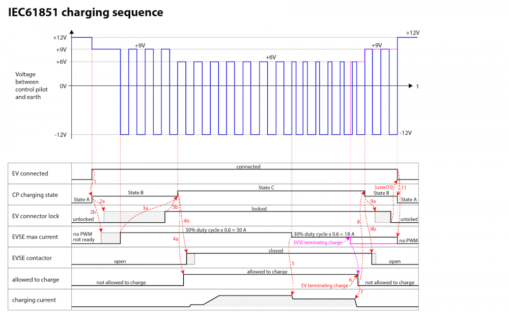
By default, the the EVSE (charging station) outputs +12V on the CP pin, and when connected to an EV will be reduced to 9V because of a load resistor present in the Electric Vehicle; this signals the EVSE that the connector has been plugged into a EV. After this, the EVSE will send a 1khz +12V to ‐12V square wave (PWM signal) and the duty cycle value corresponding to the maximum current it could deliver. If the EV is okay with that value of current, then it performs a handshake by changing the load resistance and dropping the PWM voltage to 6V, after which the charging begins.
In IEC61851, where untethered charging stations are allowed, the PP pin is used to detect the maximum power rating of the cable.
In the US, with J1772, where charging stations need to be tethered, the PP pin is used to detect if the manual unlocking mechanism is pressed, to stop the current flow before the plug is removed.
More information: https://en.wikipedia.org/wiki/SAE_J1772
CCS DC charging
DIN 70121 and ISO 15118 are quite complex high level protocols transmitted over PLC (power line communication) on the CP pin.
This Design Guide for Combined Charging Systems by CharIn describes the basics of CCS charging very well.
https://openinverter.org/forum/download/file.php?id=1712&sid=59cf27578e4021c1e6dc01c73f46d8ee
This document actually covers Fast and Smart Charging Solutions for Full Size Urban Heavy Duty Applications, but since the protocols used are similar it has comparable sequence diagrams, with descriptions for normal start up, normal shutdown, DC supply-initiated emergency stop and EV-initiated emergency stop.
https://assured-project.eu/storage/files/assured-10-interoperability-reference.pdf
References
- ↑ https://www.auto-click.co.uk/index.php?route=product/product&product_id=1344
- ↑ https://www.auto-click.co.uk/805-587-545
- ↑ https://www.auto-click.co.uk/1-967616-1
- ↑ https://www.mouser.com/ProductDetail/571-1-967616-1
- ↑ https://www.auto-click.co.uk/5-962885-1
- ↑ https://www.auto-click.co.uk/1-967067-1
- ↑ https://openinverter.org/forum/viewtopic.php?p=30636#p30636
- ↑ https://openinverter.org/forum/viewtopic.php?p=51484#p51484
- ↑ https://openinverter.org/forum/viewtopic.php?p=24613#p24613
- ↑ https://openinverter.org/forum/viewtopic.php?p=24597#p24597
- ↑ https://openinverter.org/forum/viewtopic.php?p=41590#p41590
- ↑ https://openinverter.org/forum/viewtopic.php?p=24613#p24613
- ↑ https://openinverter.org/forum/viewtopic.php?p=32096#p32096
- ↑ https://openinverter.org/forum/viewtopic.php?p=49346#p49346
- ↑ https://openinverter.org/forum/viewtopic.php?p=43848#p43848
- ↑ https://openinverter.org/forum/viewtopic.php?p=54432
- ↑ https://openinverter.org/forum/viewtopic.php?p=44069#p44069
- ↑ https://openinverter.org/forum/viewtopic.php?p=54452#p54452
- ↑ https://bimmercat.com/bmw/en/parts/info/Control+unit%2C+charging+interf.module+LIM/61356828052