Mitsubishi Outlander DCDC OBC
The Mitsubishi i-MiEV, Outlander PHEV and Minicab MiEV feature a CANBus controlled 3.3 - 3.7kW charger suitable for budget EV conversions. Units out of the Outlander PHEV are most common and can be bought for under $100. The old 3.7kW versions from the i-MiEV (pre 2013) are known to fail often and need repair. Latest versions from the Outlander seem to have V2L capabilities[1].
Part numbers from the Outlander PHEV: W005T70271 (pre 2018) [1], W005T70272 (post 2018) [2]
forum thread: https://openinverter.org/forum/viewtopic.php?t=628
3d scan cad file: https://grabcad.com/library/outlander-phev-charger-and-dcdc-1
The charger has a 3.7k ohm resistance between the CAN H and CAN L pins.
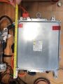
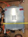
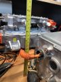
Dimensions
* Length 370mm
* Width 270mm
* Height 150mm
* Weight 12.5kg (W005T70271) / 11.7kg
-
 Length
 -
 Width
Width -
 Height


Internals:
 |
 |
|---|---|
| Bottom | Top |
DC-DC Converter
The charger has an integrated DC-DC converter outputting a fixed voltage that seems to vary some between users. 14.5V is a common value, but 14.35V and all the way up to 15V is reported. The converter requires battery voltage between 200V and 400V on the DC bus.
*at about 397v the DCDC appears to stop operating via the enable lines. Currently untested if it continues via can. [3]
To start the DC-DC converter, first to apply 12V to pin 7 and GND to pin 10. You also need to have its casing connected to common GND and 12V at the Pin 8 IGCT main power pin.
Then apply 12V ENABLE signal to pin 4 and you will see 14.5Vdc on the power line.
The DCDC is capable of at least 1800W of power. At moderate power levels, the internal temperature is not increased much.
Connections
Signal Connector
Pinout
| Pin on 13-pin Connector | DCDC Side Pin Number | Pin on Internal Connector | DCDC Side Color | Color from Schematic | Name | Function |
|---|---|---|---|---|---|---|
| 1 | 6 | Orange | NC | Not Connected | ||
| 2 | 5 | Blank | NC | Not Connected | ||
| 3 | 4 | Blue | NC | Not Connected | ||
| 4 | 3 | Grey | Violet-Green | DC SW | Enable DC/DC Converter | |
| 5 | 2 | Light Blue | Pink-Green | CHIN | Serial Protocol to EV Remote WiFi Module | |
| 6 | 1 | Black | Black-Blue | CAN H | CAN High | |
| 7 | 13 | Green | Grey | Sense | Sense for DC/DC Converter (via shared 7.5A fuse) | |
| 8 | 12 | Yellow | Light Green | IGCT | Main +12V Power Supply (via shared 7.5A fuse) | |
| 9 | 11 | White | Blue | CP | Control Pilot from Charge Port | |
| 10 | 10 | Black | Black | GND | Ground | |
| 11 | 9 | Blank | NC | Not Connected | ||
| 12 | 8 | Purple | Brown-Red / Yellow-Black | CHOT | Serial Protocol to EV Remote WiFi Module | |
| 13 | 7 | Red | Red-Blue | CAN L | CAN Low |
Note: Although the above pin numbers, for the 13 pin external connector, match the Mitsubishi wiring diagram the numbers marked on the connector are reversed for each row. Pin 1 is CAN H (Black), pin 6 is NC (orange), pin 7 is CAN L (red ) and pin 13 Sense ( green ). IGCT +12V power should not be powered permanently, this will create problems for using the charger. Recommended to only have the charger powered with Ignition on or charging.
Its not recommended to have permanent 12v supply to GND and IGCT as it will cause issues with the charger not functioning properly. The recommended wiring with the ZombieVerter is as follows:
- GND to ground
- SENSE to permanent 12v+
- IGCT to switch 12v+ via a relay controlled by a Zombie output pin set to "HVactive"
- DC SW to Zombie controlled IGN relay
This ensures the DCDC only starts drawing HV after precharge is complete, and powers down the OBC when the HV system is off. The Zombie must take care of the proximity pilot detection in order imitate charge mode, which will turn on the HV, Outlander DCDC, and start sending the correct CAN messages for charging.
External Connector

The charger is controlled via a 13-pin connector mounted on a short tail into the case. Connectors seem to be widely available to mate with this. Search for "Sumitomo 6189-1092 13-WAY CONNECTOR KIT Inc Terminals & seals [13-AC001]".
Internal Connector

In case the charger doesn't come with the signal pigtail (which it usually does), the internal signal connector is from the Hirose GT8E series[7], specifically the Hirose GT8E-12DS-HU[8] with Hirose GT8E-2022SCF[9] pins.
The External to Internal wiring harness is as follows:
| Internal Connector (Black) | External Connector (Grey) |  | ||
| Pin | Wire Colour | Pin | Function (If Known) | |
| 1 | grey | 4 | DC SW - Enable DC/DC Converter |  |
| 2 | blue | 3 | NC | |
| 3 | black | 6 | CAN H -CAN High | |
| 4 | black | 10 | GND – Ground |  |
| 5 | yellow | 8 | IGCT – Main +12V Power Supply (via shared 7.5A fuse) | |
| 6 | green | 7 | Sense - Sense for DC/DC Converter (via shared 7.5A fuse) | |
| 7 | light blue | 5 | CHIN - Serial Protocol to EV Remote WiFi Module |  |
| 8 | NC | 11 | NC | |
| 9 | orange | 1 | NC | |
| 10 | red | 13 | CAN L – CAN Low |  |
| 11 | purple | 12 | CHOT – Serial Protocol to EV Remote WiFi Module | |
| 12 | white | 9 | CP – Control Pilot from Charge Port | |
AC Power Connector

The AC power connector is Yazaki 7283-7350-30 / Toyota 90980-11413[10].

+12V DC Connector
The thread size of the +12V stud of the DC/DC converter is M8. The Mitsubishi part number for the correct cap is "MUC000691".
Charge Control
There is no voltage adjustment only current so your controller needs to monitor output voltage and step the charge current. Regardless of the set current the pilot signal will limit the charge current automatically. The pilot signal duty cycle is available on the can bus.
The OBC is capable of delivering 12A DC. Dependent on your system voltage, the power output may be limited below 3.7 kW. For example, for a 250V system, the power output is only 12*250 = 3kW.
CANBus Messages
https://github.com/haand22/Mitsubishi_Outlander_PHEV.git
The CANBus interface operates at 500kbps/100ms.
Starting charging requires two messages:
0x285 alone will connect the EVSE but won't charge until you send 0x286. Byte 2 = 0xb6 pulls in the EVSE.
0x286 byte 2 sets the DC charge current, there is a voltage setting on byte 0 and 1. The requested current should be limited to 12A, going above this results in strange current delivery. If 13A is requested, charging does not even start.
Charger will only start charging if EVSE CP is connected and requested current is below EVSE limit.
- Byte 0-1 = Voltage setpoint (Big Endian e.g. 0x0E 0x74 = 3700 = 370v)
- Byte 2 = Current in amps x 10
The charger also returns information over the CANbus:
0x377h 8bytes DC-DC converter status
- B0+B1 = 12V Battery voltage	(h04DC=12,45V -> 0,01V/bit)
- B2+B3 = 12V Supply current	(H53=8,3A -> 0,1A/bit)
- B4 = Temperature 1		(starts at -40degC, +1degC/bit)
- B5 = Temperature 2		(starts at -40degC, +1degC/bit)
- B6 = Temperature 3		(starts at -40degC, +1degC/bit)
- B7 = Statusbyte 		(0x20=standby, 0x21=error, 0x22=in operation)
-  - bit0(LSB) = Error
-  - bit1	= In Operation
-  - bit3      =
-  - bit4      =
-  - bit5      = Ready
-  - bit6	=
-  - bit7(MSB) =
0x389
- B0 = Battery Voltage (as seen by the charger), needs to be scaled x 2, so can represent up to 255*2V; used to monitor battery during charge
- B1 = Charger supply voltage, no scaling needed
- B6 = AC Supply Current x 10
- B7 = DC side current x 10 (should equal commanded current)
0x38A
- B0 = temp x 2?
- B1 = temp x 2?
- B3 = EVSE Control Duty Cycle (granny cable ~26 = 26%)
Parallel charger control:
One can use several chargers in parallel each on its own AC phase line.
Charger works good with simple 12V square PWM signal derived from DUE. So to control chargers in parallel i just need to send fake CP signal into DUE and sense the square weave to output two identical square weaves on other PWM pins. Chargers will respond to 0x286 request.
Charger voltage control:
Charger voltage control is dependent on reading its voltage reports on telegram 0x
First i request listening to CAN in main function. Of course variables need to be declared...
CAN_FRAME incoming;

if (Can0.available() > 0) {
    Can0.read(incoming);
    if (incoming.id == 0x389) {
        voltage = incoming.data.bytes[0];
        Ctemp = incoming.data.bytes[4];
    }
    if (incoming.id == 0x377){
        aux1 = incoming.data.bytes[0];
        aux2 = incoming.data.bytes[1];
        auxvoltage = ((aux1 * 256) + aux2); //recalculate two bit voltage value
    }
}
I request charger command telegram function and within i condition for high voltage reduction and stop.
void sendCANframeA() {
	outframe.id = 0x286; // Set our transmission address ID
	outframe.length = 8; // Data payload 8 bytes
	outframe.extended = 0; // Extended addresses - 0=11-bit 1=29bit
	outframe.rtr=1; //No request
	outframe.data.bytes[0]=0x28;
	outframe.data.bytes[1]=0x0F; // 0F3C=3900, 0DDE=3550, 0,1V/bit

	if(voltage < 193) { // if Charger senses less than 386V
		outframe.data.bytes[2]=0x78; // 78=120 12A, 50=80 8A, 32=50 5A, 1E=30, 3A 14=20 2A at 0,1A/bit
	}
	else if(voltage <= 194) { // if Charger senses less than or equal 388V
		outframe.data.bytes[2]=0x1E;
	}
	else {  //any other case
		outframe.data.bytes[2]=0x00;
	}

	outframe.data.bytes[3]=0x37; // why 37?
	outframe.data.bytes[4]=0x00;
	outframe.data.bytes[5]=0x00;
	outframe.data.bytes[6]=0x0A;
	outframe.data.bytes[7]=0x00;

	if(debug) {printFrame(&outframe,1); } //If the debug variable is set, show our transmitted frame

	if(myVars.CANport==0) Can0.sendFrame(outframe); //Mail it

	else Can1.sendFrame(outframe);
}
DCDC aux voltage control
I can also control 12V aux battery charging by reading DCDC report on 0x377. When aux voltage drops too much i can start DCDC or 3 minutes and 12V battery gets charged up.
if (auxvoltage < 1200) { // if aux voltage is low and DCDC is off
    auxState = true; // set the flag to true

    elapsedtime = millis();
}

DCDCauxcharge();
Within this function then i compare status and count down 3min for the charge event
void DCDCauxcharge() {

    if ((auxState == true) && (digitalRead(Enable_pin) == LOW)) { // auxvoltage went below 12.2V
        digitalWrite(DCDC_active, HIGH);

        if (millis() - elapsedtime >= ontime) { // if aux voltage is low and for 5min
            digitalWrite(DCDC_active,LOW); // turn off DCDC_active relay

            elapsedtime = millis();
            auxState = false;
        }
    }
    else { // if auxvoltage is OK
        auxState = false; // turn off DCDC_active relay
    }
}
Lots of other functions can be prepared on basis of CAN report reading. Those are some functions that are usefull.
References
- ↑ https://www.mitsubishi-motors.com.au/blog/a-battery-on-wheels-why-EVs-can-do-more-than-just-take-you-places.html
- ↑ http://mmc-manuals.ru/manuals/outlander_phev/online/Service_Manual_2014/2019/index_M1.htm (Backup: Web Archive)
- ↑ http://mmc-manuals.ru/manuals/outlander_phev/online/Service_Manual_2014/img/90/HKAE0E05AC00ENG.pdf (Backup: Web Archive)
- ↑ http://mmc-manuals.ru/manuals/outlander_phev/online/Service_Manual_2014/img/90/HKAE0E05BC00ENG.pdf (Backup: Web Archive)
- ↑ http://mmc-manuals.ru/manuals/outlander_phev/online/Service_Manual_2014/img/90/HKAE0E05CC00ENG.pdf (Backup: Web Archive)
- ↑ http://mmc-manuals.ru/manuals/outlander_phev/online/Service_Manual_2014/img/90/HKAE0E06AC00ENG.pdf (Backup: Web Archive)
- ↑ https://www.hirose.com/de/product/document?clcode=CL0758-0051-6-00&productname=GT8E-12DS-HU&series=GT8E&documenttype=Catalog&lang=de&documentid=D49379_en (Backup: Web Archive)
- ↑ https://www.mouser.de/ProductDetail/798-GT8E-12DS-HU
- ↑ https://www.mouser.de/ProductDetail/798-GT8E-2022SCF
- ↑ https://www.auto-click.co.uk/7283-7350-30?search=90980-11413 (Backup: Web Archive)