ZombieVerter VCU
Now available for general sale here.
Development continues and you can
follow and contribute along with the development here on the forum
Support is available via a separate thread on the forum
Introduction
Rather than crack open inverters and swap components about to drive them, what if we simply send them the messages they're expecting? This has been the case with a couple of existing designs (Nissan leaf inverter and GS450H) and thanks to the SAM3X8E microcontroller no longer being stocked by JLCPCB this project looks to take it further.
So rather than driving an inverter powerstage this version sends CAN for the Leaf inverter or Sync serial for the GS450H and of course can be expanded to any number of others. This will be the default firmware for all vcu products from now on and future hardware will support future fun packed stuff like FLEXRAY!!!
It's basically an rip off homage and builds on other people's hard work in the shape of the following projects
- STM32-CAR project
- Openinverter
- ISA library
- Leaf inverter driver by Celeron55
What we have as of now is the openinverter wrapper with things like :
- Throttle cal and mapping,
- Precharge and contactor control,
- Temp derating,
- BMS limits,
- for/rev/neutral control,
- Graphing and monitoring,
- Firmware updates via the web interface,
- Cruise control,
- Fuel gauge driver,
- etc
Hardware
So you've ordered your kit, first things first, watch the following video to assemble it.
Due to chip shortages (written summer 2021) the board isn't fully assembled so you will need to do some soldering, or take it to a local phone repair shop (or similar) who'll find soldering at this scale like playing with Duplo.
The enclosure kit links:
Enclosure Kit with Header, connector and pins :
https://www.aliexpress.com/item/32857771975.html?spm=a2g0s.9042311.0.0.39f24c4dWOmGPE
Prewired connector with 3M leads :
https://www.aliexpress.com/item/4001213569338.html?spm=a2g0o.cart.0.0.366c3c00qhBvGO&mp=1
<youtube>https://www.youtube.com/watch?v=geZuIbGHh30</youtube>
<youtube>https://youtu.be/MUhs9j9R9Mg</youtube>
Note that in addition to the VCU, the inverter and transmission, you will require a specific canbus connected shunt: Isabellenhütte Heusler
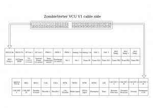
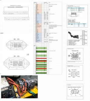
Pin Out Diagram


Further information for a GS450 system can be found here: Lexus GS450h Inverter
Note: In the software port 0 = EXT2 and port 1 = EXT
Software
https://github.com/damienmaguire/Stm32-vcu/tree/LIM_ST107
The VCU is configured by connecting to its wifi access point. For existing units this is something like SSID: ESP-03xxxx, no password. For future units (shipped after 20/10/21) this will be SSID: inverter PASSWORD: inverter123
Then navigate to 192.168.1.4 to see the huebner inverter dashboard.
Initial start-up and testing (Instructions for GS450H application)
Get familiar with the interface and check that all of the parameters make sense. If in doubt, make sure the default value is set. At each stage the current state of the system and any error can be seen on the interface, for example opmode and lasterr. Press refresh at the top of the screen to update the values.
You will need the HV power connected, which can be a lower voltage (50-100V), current limited power supply for test purposes. Set udcmin to some value below that (e.g. 50V for a 100V supply) and udcsw to 10V less than the supply.
- Apply the Ignition T15 in 12V signal. The relay supplying 12V to the inverter should now be on.
- Check the accelerator by applying it gradually and watching / refreshing the interface. You should see values at pot change as the pedal is pressed. potmin should be set just above where your off-throttle position is, and potmax just below the value seen at maximum travel. Same for pot2min and pot2max, if they are electrically connected. The resulting value as a 0-100 value can be seen at potnom.
If it does not show up, check for errors and check that throtmax is not set to zero!
- Apply the Start 12V signal for a short time. The pre-charge relay should turn on, and the voltage available at the inverter and the udc input of the ISA shunt should quickly rise. If the udc reading goes above udcsw within 5 seconds then the main contactor(s) should close.
If you do not see a good value at udc, it may be that your external shunt is not connected properly or is not initialised.
If you do not see a good value at Invudc, it may be that the inverter is not powered, or the communication signals are not correctly wired.
- Once the contactors are on, select forwards direction. For example if dirmode is set to "Switch" then a 12V signal applied to the Forward input will work.
- Carefully apply the accelerator and the motor should begin to turn. Do not spin the motor up to any speed if you are using a test power supply.
Supported OEM Hardware
- Nissan Leaf Gen1/2/3 Inverter/ motor
- nissan leaf gen 2 drive stack (inverter, dcdc, charger) gen 3 coming soon
- Lexus GS450H inverter / gearbox via sync serial
- Toyota Prius/Yaris/Auris Gen 3 inverters via sync serial
- chevy volt HV water heater
- BMW E46 CAN support
- BMW E39 CAN support
- BMW E65 CAN Support
- CCS DC Fast Charge via BMW i3 LIM