Tesla Model S/X DC/DC Converter: Difference between revisions
m →LV & Signalling: Minor formatting fix in an image caption. |
m →HV: Removed some extraneous boldface. |
||
| Line 23: | Line 23: | ||
Donor Harness: Tesla OE/OEM Part Number: 1032804-00-A has two Blue DC-DC plugs. | |||
[[File:PXL 20210514 092652934-min.jpg|alt=Pinout for LV connector is written on the board|thumb|Pinout for LV connector is printed on the board.]] | [[File:PXL 20210514 092652934-min.jpg|alt=Pinout for LV connector is written on the board|thumb|Pinout for LV connector is printed on the board.]] | ||
Revision as of 00:19, 1 April 2023
Overview
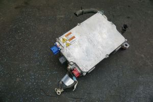
The Tesla Model S/X GEN2 DC-DC Converter is a popular candidate for EV conversions. It was first available in the Model S around Jan2014, and later in the Model X. It is located in the frunk area near the cowl.
It is not to be confused with the earlier GEN1 DC-DC Converter, whose casing was of a kidney-shape, was located in the RF fenderwell against the firewall, and it incorporated functions of the front HVJB; it contains fuses for the coolant heater, cabin heater, and air-condition compressor, and servicing these fuses was never supported by Tesla (though is frequently performed in the aftermarket), so it developed a reputation for being unreliable due to frequent replacement for blown fuses. Though the hardware connections are different between GEN1 & GEN2, they both use the same (5) wired connections with the same functions, and the CAN commands appear to (may be) the same.
Wiring
HV
HV connector: KET MG655776 type D
HV+ (positive) line is the one on the leftmost - opposite side of the red 12v output bolt.
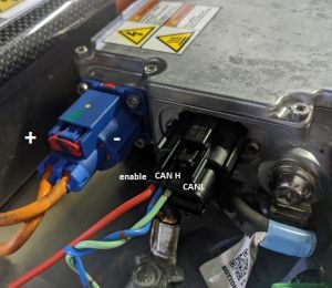
Note, be careful about which connector you get when salvaging this connector from Telsa wiring harnesses. Specifically, you want the key D variant.
- Orange (A/C): MG655773 (key A)
- Gray (fluid heater): MG655774 (key B)
- Brown (PTC heater): MG655775 (key C)
- Blue (DC-DC): MG655776 (key D)
Donor Harness: Tesla OE/OEM Part Number: 1032804-00-A has two Blue DC-DC plugs.
LV & Signalling
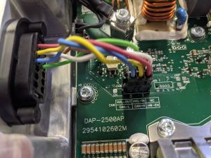
LV connector: Molex 0334721301
LV connector (top row)
- Pin 1 : HW-EN (Enable ("turn on") via applying 12v+ )
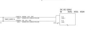
- Pin 2 : CAN H
- Pin 3 : CAN L
The remaining pins are for the HVIL loop, and can be ignored if desired, as they do not affect the unit's function.
Control
Hardware
Although CAN control is an option, it is not necessary as the unit will run comfortably in failsafe mode (i.e. without any CAN input). Supply 12V to HW-EN (pin 1 on Molex plug), ground the case to the chassis, and the converter starts spitting out 13.5V. It has been mentioned that under heavy load the voltage may sag, so to enable CAN control see this OI forum thread.
CAN
Two CAN MsgIDs are documented for this unit:
- 0x03D8 : Input: Commands to the unit (3 bytes)
- 0x0210 : Output: Status Reporting from the unit (7 bytes)
Commands (0x03D8)
This CAN command payload is 3 bytes, and must be sent at 500ms intervals.
The first 10 bits (0-9, little-endian format) in the message encodes the output voltage. The following bit is the DC/DC enable bit[1]:
- Byte 0 + Byte 1[0-1] (10 bits total) : (desired voltage - 9) * 146)
- Byte 1[2] = Enable DC output (must be 1 to enable output)
- Byte 1[3-7] : Unknown
- Byte 2 : Unknown
Example
If 14.4V is desired:
- Subtract constant 9 from 14.4v = 5.4
- Multiply 5.4 by constant 146 = 788.4
- Convert 788.4 to hex = 0x0315 (expressed as individual bytes: 0x03 0x15)
- Convert to little-endian format = 0x15 0x03
- Add 4 to the second byte, to enable DC output = 0x15 0x07
- Pad with zero byte to assemble the required 3-byte payload: 0x15 0x07 0x00
- Prefix with the command MsgID 0x3D8 : 0x03D8 0x15 0x07 0x00
- Send the MsgID + data payload
Status Reporting (0x0210)
The data is comprised of 7 bytes, which is transmitted at 100ms (10Hz) intervals:
- Byte 2 = coolant inlet temp,
- Byte 3 = input power (16 W/bit),
- Byte 4 = output current (1 A/bit),
- Byte 5 / 10 = output voltage (0.1 V/bit)
Note Status Reporting does not work if HW-EN line is not high.
Jason Hughes (wk057) posted this DC-DC Converter CAN Status Reporting information[2] in Jan2016:
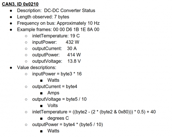
The "CAN3" above refers to the specific CAN bus on the early Tesla Model S, which had (5) (later, (6)) CAN buses. CAN3 is the Powertrain CAN bus.