Tesla Model S/X Large Drive Unit ("LDU")
Overview

The Tesla Model S/X Large Drive Unit (LDU) was the first drive unit produced by Tesla dating back to the launch of the Model S in 2012. Applications include RWD Model S & X, as well as performance AWD S & X - in both cases serving as the rear drive unit.
Specs:
- Weight: 291 lbs (132 kg)
- Input Voltage: 240-404V DC
- Power: 335 kW (~450HP) to 475 kW (~636 HP) depending on configuration
- Torque: 450 Nm (~332 ft/lb) to 650 Nm (~480 ft/lb) depending on configuration
- Max RPM: 18,000
- Gear ratio: 9.73:1
Connections
Overview


Low-Voltage
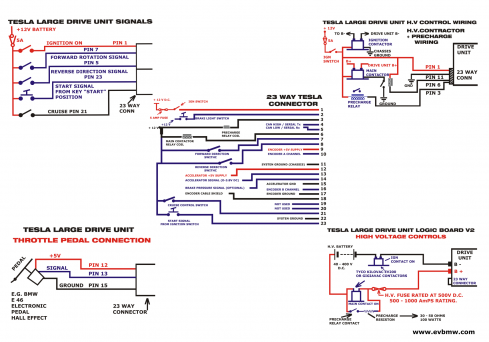
Main I/O Plug
The main low-voltage connector is a 23-pin socket from the TE AMPSEAL family:
- Housing (F): 770680-1
- Pins (F): 770520-1 (20-16 AWG)
Connector Mapping/Pinout
| PIN NUMBER | OEM | OPEN SOURCE |
| 1 | IGN +12V | IGN +12V |
| 2 | BRAKE ON N.O. | BRAKE ON |
| 3 | BRAKE OFF N.C. | PRECHARGE RELAY |
| 4 | CAN HIGH | CAN HIGH |
| 5 | CAN LOW | CAN LOW |
| 6 | CHG PROXIMITY | MAIN CONTACTOR |
| 7 | HVIL IN | FORWARD |
| 8 | HVIL OUT | REVERSE |
| 9 | ENC +5V | ENC +5V |
| 10 | ENC A | ENC A |
| 11 | GND | GND |
| 12 | ACCEL 1 +5V | ACCEL 5V |
| 13 | ACCEL 1 | ACCEL INPUT |
| 14 | ACCEL 2 | BRAKE TRANSDUCER |
| 15 | ACCEL 1 GND | ACCEL GND |
| 16 | ENC B | ENC B |
| 17 | ENC GND | ENC GND |
| 18 | ENC SHIELD | ENC SHIELD |
| 19 | CAN HIGH OUT | |
| 20 | CAN LOW OUT | |
| 21 | ACCEL 2 +5V | CRUISE IN |
| 22 | ACCEL 2 GND | GND |
| 23 | 12V ALWAYS T30 | START |
Encoder Plug
A smaller 4 pin LV connector is responsible for the encoder signals. The plug is TE 444046-1; this part is EoL from TE, however the connector is widely available on Aliexpress.
Per the Tesla Large Drive Unit Support Thread :
- Pin 1 of the Encoder connector to Pin 17 of the 23way ampseal main connector
- Pin 2 of the Encoder connector to Pin 16 of the 23way ampseal main connector
- Pin 3 of the Encoder connector to Pin 10 of the 23way ampseal main connector
- Pin 4 of the Encoder connector to Pin 9 of the 23way ampseal main connector
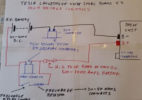
Contactors
Please note that the contactors you purchase *may* have polarity associated with them for the low voltage control signal. If you have problems related to the pre-charge circuit working, or contactors behaving as not expected, check this!
High-Voltage
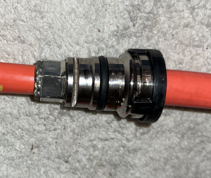
The OEM LDU HV cables' insulation OD is ~.680" (17.3mm) (verified for the "early" Model S units). The HV cables are EMC shielded, and use proprietary EMC cable glands which are not available separately. Fellten supplies custom aftermarket cable glands to fit the LDU's case and aftermarket 70mm2 shielded cabling[1]. The early Model S LDU cables are ~44" (1120mm) in length. One part No. for the cables set is 1004872-00-B.


The OD of the casting where the external o-ring is located is ~1.030" (26.2mm). The OEM gland nuts are plated and are often found in a corroded state.
Tesla Large Drive Unit Logic Board
An openinverter based control board has been made available by Damien Maguire. A "community edition" (i.e. mostly complete) version is available here on the OI webshop, or you can have your own made from info contained in Damien's LDU github repo.
This board replaces the original board that comes with the OEM Tesla drive train. As opposed to the latter, this board lets you use the drive train in the first place and allows you to fine-tune driving behaviour with the usual set of openinverter parameters. It does not restrict you in power output or regen input.
You can fully control the board via CAN or via a set of digital and analog inputs.
Application Info
If you buy the board from the openinverter shop it comes programmed with a recent software version. Please check github for recent software releases. In addition the board comes with a set of parameters appropriate to run the Tesla LDU. So it will work out of the box. Parameters that must not be changed are hidden to eliminate sources of error.
You will need to solder the supplied connectors to the board. The drive unit connectors will plug right in.
To test run your drive unit, supply the board with 12V and GND on the Ampseal connector. Also supply 12V „Forward“ to select forward direction.
Supply inverter with some high voltage. For first tests it is recommended to put a large resistor/heating element/kettle in series.
You can start in manual mode using the button on the web interface and enter like 1Hz for „Fslipspnt“ and some value between 10-50 for „ampnom“ to see if the motor spins up. Be careful because manual mode does not enforce a motor speed limit! However, „Fslipspnt“ sets the base speed requested of the motor. Setting it to 1Hz will spin the motor very slowly. Setting it to 5, 10, or 15Hz will spin it progressively faster. For any given speed you will need to experiment with „ampnom“ to find a happy place where enough current is allowed to flow but not too much. Finding a good set of values should make your motor spin reasonably smoothly. Also check the „Boost“ as it may require an increased value of 5000-10000.
You may also set parameter „udcsw“ and „udcmin“ to 0 and start drive mode by pulsing 12V on „Start“. Then connect a pot between 5V, GND and „Pot“ (wiper). This will also spin the motor AND enforce a speed limit.
By default the inverter is controlled as above - by using digital I/O and directly connecting an accelerator pedal. However, it is also possible to control it directly over CAN: CAN communication
CAN control could be used to control the inverter via an external VCU such as the Zombie (not yet supported).
Additional Resources
Tuning and Parameters
There are several tuning threads and sets of shared parameters on the Open Inverter Forum. The two most useful collections are: Original Parameter Sharing Thread and the Tuning Discussion Thread.
The tuning guide here has lots of useful information regarding the impact of various parameters on the LDU.
The main Open Inverter parameter definition page is located here.
Throttle Wiring

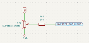
The Tesla LDU drop in board uses a range of 0-3.3V for the throttle input, however many OEM throttle pedals use a range of 0-5V. This can work, however it presents an issue in the event of a broken throttle pedal. A fix has been implemented in the firmware as of June 2024, which requires a 10k resistor placed in line on the throttle signal. Read more in this thread.
Failure Modes
Encoder Issues
It is not uncommon to have issues with the encoder on these drive units. The encoder is connected via a 4 wire cable from the 23 pin external connector of the drive unit to the encoder which is situated on the opposite side of the drive unit. The biggest sign of encoder problems is the motor "bucking" back and forth and not wanting to spin properly in the requested direction. It may spin the direction you've asked for but roughly and with great trouble. This situation needs to be corrected. There are a number of things that could be wrong:
- The wires may be broken. You should attempt a continuity check of each of the wires.
- The encoder signals may be backward. There are two channels - A and B. They must be presented to the inverter in the proper order. If this is in doubt, try swapping them.
- One of the encoder signals may be missing. As above, there should always be two channels. They're "quadrature" which means that they fire 90 degrees apart.
To check the encoder signals you should have either a logic analyzer or an oscilloscope. Both come in a wide range of prices. The encoder signal is not particularly fast, especially when the motor is not spinning that fast. As such, even cheap test equipment can be adequate. You may find that there is no particularly good place to connect to in order to read the encoder signals. But, there does exist a reasonable place - right at the 20 pin connector on the LDU board where the 23 pin external connector's wires are routed. If your logic analyzer or oscilloscope has little grabber adapters you can do something like in this picture:

The pins on this connector are numbered starting with 1 at the far right and going more positive toward the left until you get to pin 20.
| Pin Number | Function |
|---|---|
| 5 | Encoder 5V Source |
| 6 | Encoder A Channel |
| 7 | Encoder B Channel |
| 8 | Encoder Ground |
So, in the picture, channel 0 is connected to encoder 5v (to monitor that voltage is properly there), channel 1 is connected to the A channel of the encoder, channel 2 is connected to the B encoder channel, and scope ground is connected to the encoder ground wire. This allows for monitoring all of the relevant signals. But, keep in mind not to short any pins while doing this. Very fine probes will be needed and extreme caution not to clip two pins together. The clips/grabbers in this picture are from a Saleae Logic Pro 8. This is *NOT* your cheapest option for monitoring encoder signals but does work very well. It also doubles as a 50Mhz oscilloscope which can be handy. Cheaper options (including knock offs of Saleae Logic) do exist.
Here is a picture of what it may look like when one encoder signal is missing:

Another good way to check the encoder is to use the steps to enter manual mode but do not set "Fslipspnt" nor "ampnom". You need to not be in "Off" mode. In Off mode the speed and turns values do not update in the spot values. But, in manual mode they do. So, enter manual mode without asking for any speed, then turn the motor. With the motor spinning you should see some position feedback in the form of a non-zero speed value and the turns value should increment. If these things do not reliably occur then you may still be having encoder problems. If they do occur, still check to ensure that your A and B channels are the right way around.
Internal Coolant Leaks
The Tesla LDU is famous for springing a leak on the motor side. Right there at the inlet there is a seal to the motor shaft. It fails then coolant starts to seep into the motor itself. This rusts the hell out of the motor internally until so much sludge builds up that it looks like a mud pie. Obviously, that is less than ideal. One way to check for this sort of thing is to go to the motor side and remove the one bolt that holds the encoder into the motor housing. If the encoder is soaking wet inside or looks like there is a slurry of liquid poo in the motor then there is bad news.
I'm not sure if there is any good pathway from the motor leak to the inverter so they could be two separate issues. In fact, having taken one apart, I guess that's almost certainly the case. But, the inverter has coolant running to it as well.
Anyway, still check the encoder because that part is famous for leaking too and it ruins the motor.
Long term, a leaking seal will develop. Full coolant loop delete as well as performance alternatives that retain cooling for towing and racing applications are available for install to solve leaking seals in LDUs.[1][2][3]
- https://revoltsystems.com/tesla-large-drive-unit-ldu-coolant-bypass-kit-the-achilles-seal-fix/
- https://www.westside-ev.com/store/p/pfi-fersa-coolant-delete-manifold
- https://qccharge.com/collections/coolant-delete
Over Current Events
Many conversions using the Tesla LDU with the Open Inverter drop in board run into frequent Over Current errors, especially while tuning, and often despite remaining below the programmed over current parameter. These events also seem unusual because the board will require a full power cycle, rather than just a new start input, in order to restart. It is believed that what is actually occurring is a desaturation event, which the Tesla gate drivers are catching and shutting down, and the board is reporting as an over current event. The full power cycle is necessary to reset the gate drivers. Lowering fslipmax appears to address the issue in most cases.
Other considerations
The motor itself will run as well in the reverse direction as in the forward direction. However if you are running the gearbox integrated with the drive unit in reverse you will want to replace the gearbox's oil pump with a reverse oil pump. These can be found on ZeroEV. [1]
CAD
An amazing-quality solid model of this drive unit has been made available on GrabCAD by Winston Jennings.