Nissan Leaf Gen2 Board

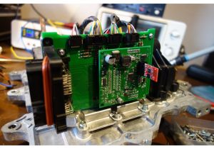
The Nissan Leaf gen 2 board is a replacement mother board for the gen 2 leaf inverters. it utilizes a adapter board to fit a rev 3 openinverter board in into the leaf inverter.
- Full control over the nissan power stage.
- power beyond the stock 80kw. (up to140kw (or more?))
- wifi interface + tuning
- OTA software updates and parameters
- regen and cruise control
The Kit

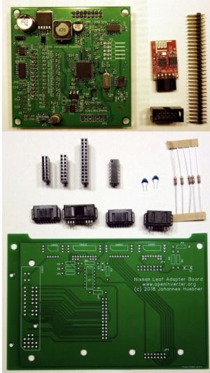
The kit comprises of:
- openinverter rev3 board pre programmed with leaf motor tune
- Esp8266 wifi board
- adapter board
- various connectors
- a handful of some basic components
The kit is designed to drop in place of the original Nissan logic board. The adapter board is designed to re-use the large proprietary connector that is mounted on the original logic board.
Kit shop link: https://openinverter.org/shop/index.php?route=product/product&product_id=57
Nissan Board Removal

The inverter casing attaches directly to the motor.
- remove the inverter from the motor:
- remove the 2 torrox screws holding the inverter/motor phase wire connection cover on.
- remove the 3 exposed hex head bolts. each bolt is a phase connections, keep these separate from the rest of the bolts
- lift the inverter off the motor, be carful not to bend or nock the coper phase connections.
- taking the inverter apart
- remove the 4 10mm hex head bolts around the connector(?)
- remove the connector(?) cover
- remove all the hex head bolts around the inverter
- with a mallet tap around the seam in the inverter casing to loosen the sealant
- pry the case open, carefully lift the 2 case half's apart.
- removing the mother board
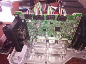
the oem mother board is easly distinguished as it has the large proprietary connector attached. It is on it's own aluminum bracket attached to the case by 3 allen head bolts.
- disconnect the plugs from the four connectors at the top of the board.
- remove the allen bolts to free the bracket and board.
- remove the screws holding the board to the bracket Nissan uses some very strong thread lock so be prepared for some of the screw heads to shear.*carefully heating the screw will help break down the thread lock


Once the board has been removed from the carrier,the large connector must be salvaged from it. One method is shown in the swap video, a vacuum soldering iron is also known to work.
Swap video: https://www.youtube.com/watch?v=T_6hw6vGzfM
Kit Build
- Solder the components to the board as per the instructions.
- The large proprietary connector must be salvaged from the original Nissan logic board. as it is not available on the open market. once salvaged, solder it onto the adapter board.
- plug in the rev 3 board and wifi adapter.
- clean up the wiring harness
- connect 12v to power up the board and test that it is working. login to the wifi interface.
- Use fresh screws to attach the board to the carrier and bolt it back in place using the allen head screws.
- connect the gate drivers to the adapter board
- see rev3 board page
Proprietary Connector
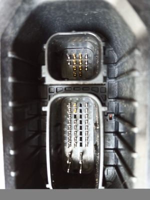
Not all pins of the connector are available. The top group are blanked off, so the brake and BMS signals are not available.
The resolver and CAN bus signals remain on the same pins as used by Nissan. If other signals are required then they must be added to the female connector.
Part numbers for this connector can be found here: Connector Part Numbers
The Toyota hybrid series car inverters (Gen 3 Prius confirmed) use the same connector.
part number for matting connector g926047010 (undertested on the leaf but seems to fit Prius gen 3 https://openinverter.org/forum/viewtopic.php?p=12668#p12668)
A 3D printable plug for the 35pin ampseal connector may work in this instance.(originally designed for the Prius gen 3 inverter)
https://openinverter.org/forum/viewtopic.php?f=14&t=836
orginal form post with a set of variants
https://openinverter.org/forum/viewtopic.php?f=14&t=488&start=100#p11671
There are multiple part numbers for the large 35 way Ampseal through hole socket, with small mating differences, be sure to get a matching pair.
TE connectivity 776164-1 and 776163-1 are a matched pair. Look for the male connector that comes with a gasket. ( these are a right angle pin connector, the straight pin might be a better option)
Wiring
the adapter board in the kit is set up so the original oem wiring harness works with the open inverter board.
Contactors:
The output driver(uln2003) on the openinverter board pulls to ground, so connect the negative lead of your pre charge contactor to OUT_PRE (pin 43) and the negative lead of your positive contactor to OUT_DCSW(pin42)
positive leads connected to fused 12v
Most conversions have the negative contactor switch on via the ignition key.
throttle/break pedal wiring:
wiring is based on the parameters you chose in the web interface:
dual channel throttle:
whipper lead 1 -> THROTTLE1 (pin 29)
whipper lead 2 -> THROTTLE2 (pin 28)
positive lead(s) -> 5v (pin26)
negative lead(s) ->GND (pin47/49)
throttle/regen:
channel 1 throttle
channel 2 break pedal (for variable regen)
throttle pedal whipper lead 1 -> THROTTLE1 (pin 29)
brake pedal whipper lead -> THROTTLE2 (pin 28)
positive leads -> 5v (pin26)
negative leads ->GND (pin47/49)
Leaf OEM pre-wired connections
if using the oem leaf connector, the following connections are already populated:
- resolver
- motor temp
- power
- main contactor
- can high/low
Diagram found here: http://productions.8dromeda.net/c55-leaf-inverter-protocol.html
+-----------------------------------+  +------------+
| 47   46   21 20 19 18 17 16 15 14 |  |       x  x |
|           29 28 27 26 25  x 23 22 |  |  6 x  x  x |
| 49   48    x  x  x  x  x  x  x  x |  | 10 x  x  x |
|           45 44 43 42 41 40 39 38 |  |    x  x  x |
+-----------------------------------+  +------------+
| - 6 = OUT_BRAKE |
| - 10 = IN_BMS |
| - 14 = CANH * |
| - 15 = CANL * |
| - 16 = IN_FORWARD |
| - 17 = RES_S2 * |
| - 18 = RES_S4 * |
| - 19 = RES_R1 * |
| - 20 = RES_S1 * |
| - 21 = RES_S3 * |
| - 22 = IN_START |
| - 23 = IN_BRAKE |
| - 25 = IN_REVERSE |
| - 26 = 5V |
| - 27 = RES_R2 (GND) * |
| - 28 = THROTTLE2 |
| - 29 = THROTTLE1 |
| - 38 = IN_CRUISE |
| - 39 = OUT_PWM |
| - 40 = OUT_ERR |
| - 41 = OUT_OVTG |
| - 42 = OUT_DCSW * (! 12V input on original harness, make sure not to connect to 12V but to DC switch!) |
| - 43 = OUT_PRE |
| - 44 = MTEMP1 * |
| - 45 = MTEMP2 * |
| - 46 = 12V * |
| - 47 = GND * |
| - 48 = 12V * |
| - 49 = GND * |
| Only pins with * are populated on the OEM wire harness |
Self-Printing
The Leaf adapter board can be self-printed from gerber files (e.g. with JLCPCB), with two caveats for the SMD version:
- when populating the board IC1 needs to be a 5V tolerant AND gate (not NAND), e.g. MC74HC1G08DTT1G
- the rear plane is at 5V, so a little plastic disc or similar needs to be added to avoid charging the inverter casing at 5V