Tesla Model S/X Large Drive Unit ("LDU"): Difference between revisions
No edit summary |
(Added parameter link) |
||
| Line 4: | Line 4: | ||
[https://openinverter.org/shop/index.php?route=product/product&product_id=64 Purchase in openinverter shop] | [https://openinverter.org/shop/index.php?route=product/product&product_id=64 Purchase in openinverter shop] | ||
[https://openinverter.org/parameters/view.html?id=16 Parameters] | |||
=== Ampseal Connector Mapping === | === Ampseal Connector Mapping === | ||
Revision as of 09:40, 5 April 2021
The Tesla Model S/X Large Rear Drive Unit...
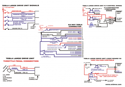
Ampseal Connector Mapping
| PIN NUMBER | OEM | OPEN SOURCE |
| 1 | IGN +12V | IGN +12V |
| 2 | BRAKE ON N.O. | BRAKE ON |
| 3 | BRAKE OFF N.C. | PRECHARGE RELAY |
| 4 | CAN HIGH | CAN HIGH |
| 5 | CAN LOW | CAN LOW |
| 6 | CHG PROXIMITY | MAIN CONTACTOR |
| 7 | HVIL IN | FORWARD |
| 8 | HVIL OUT | REVERSE |
| 9 | ENC +5V | ENC +5V |
| 10 | ENC A | ENC A |
| 11 | GND | GND |
| 12 | ACCEL 1 +5V | ACCEL 5V |
| 13 | ACCEL 1 | ACCEL INPUT |
| 14 | ACCEL 2 | BRAKE TRANSDUCER |
| 15 | ACCEL 1 GND | ACCEL GND |
| 16 | ENC B | ENC B |
| 17 | ENC GND | ENC GND |
| 18 | ENC SHIELD | ENC SHIELD |
| 19 | CAN HIGH OUT | |
| 20 | CAN LOW OUT | |
| 21 | ACCEL 2 +5V | CRUISE IN |
| 22 | ACCEL 2 GND | GND |
| 23 | 12V ALWAYS T30 | START |
Tesla large drive unit logic board
This board replaces the original board that comes with the OEM Tesla drive train. As opposed to the latter this board lets you use the drive train in the first place and allows you to fine-tune driving behaviour with the usual set of openinverter parameters. It does not restrict you in power output or regen input.
You can fully control the board via CAN or via a set of digital and analog inputs.
Application Info
If you buy the board from the openinverter shop it comes programmed with a recent software version. Please check github for recent software releases. In addition the board comes with a set of parameters appropriate to run the Tesla LDU. So it will work out of the box. Parameters that must not be changed are hidden to eliminate sources of error.
You will need to solder the supplied connectors to the board. The drive unit connectors will plug right in.
To test run your drive unit, supply the board with 12V and GND on the Ampseal connector. Also supply 12V „Forward“ to select forward direction.
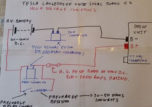
Supply inverter with some high voltage. For first tests it is recommended to put a large resistor/heating element/kettle in series.
You can start in manual mode using the button on the web interface and enter like 1Hz for „Fslipspnt“ and some value between 10-50 for „ampnom“ to see if the motor spins up. Be careful because manual mode does not enforce a motor speed limit!
You may also set parameter „udcsw“ and „udcmin“ to 0 and start drive mode by pulsing 12V on „Start“. Then connect a pot between 5V, GND and „Pot“ (wiper). This will also spin the motor AND enforce a speed limit.

