FoccciCape

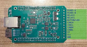
This is an add-on board for the popular BeagleBone single board computer. It is mainly a communication breakout board but features a very special form of communication: CCS! So with it you can get your EV to close its charge port contactors. At the very least you can then charge your EV with your hybrid PV inverter and if the manufacturer doesn't actively inhibit it you can also draw energy from your vehicles battery to supply your house or even selling it back to the grid.
In addition it has enough communication power to talk to all sorts of PV inverters, BMSes etc. to tie it all together an fully control the flow of energy from a single point.
Connections
The board has a 12-way Phoenix connector or can be equipped with any other 3.81 mm pin pitch terminal. Together with the BeagleBone it offers the following interfaces:
- 1x RS485
- 2x CAN
- 1x CCS PowerLine communication and PWM signalling
- 2x open drain relay outputs
- 1x status LED output combined with button input
- 1x Ethernet (on BeagleBone)
- 1x USB (on BeagleBone)
- 1x HDMI (only BeagleBone Black)
- 1x Grove I2C (only BeagleBone Green)
- 1x Grove UART (only BeagleBone Green)
Software

The software is comprised of a bunch of python scripts that exchange information via MQTT. The following modules are available:
- Communication via Modbus using Modbus4Mqtt
- Communication with SoyoSource inverters
- Simulation of BYD battery via CAN
- Communication with Eltek Flatpack chargers
- Reading status from Keba P20 EVSE
- Communication with Manson switch mode power supply
- Communication with openinverter 16-cell BMS
- Retrieval of spot market prices via awattar or Tibber API
- Data logger
- Submission of raw meter data to Tibber
- CCS communication via PyPLC
- Energy flow controller (Zero Grid Exchange, charge on low spot market price, discharge only on high spot market price)
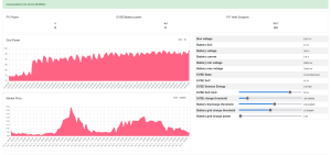
- Web Interface for configuration and monitoring
Installation
This section is only relevant if you're setting up the BeagleBone yourself. If you buy a preprogrammed one from the shop (not yet available) this has already been done for you. We are also working on an image file that is already set up.
The howto for compiling the QCA kernel module and setting it up can be found on the forum.
Next you need to flash the SPI flash on the cape with QCA firmware, this is also described on the forum.
Finally you enable all relevant peripherals in /boot/uEnv.txt:
uboot_overlay_addr0=/lib/firmware/BB-CAN0-00A0.dtbo
uboot_overlay_addr1=/lib/firmware/BB-CAN1-00A0.dtbo
uboot_overlay_addr2=/lib/firmware/BB-SPI0-QCASPI-00A0.dtbo
uboot_overlay_addr3=/lib/firmware/BB-UART4-00A0.dtbo
To enable both CAN interfaces at boot you configure systemd-networkd by creating one file per interface, /etc/systemd/network/80-can0.network
[Match]
Name=can0

[CAN]
BitRate=500K
RestartSec=100ms
And likewise 81-can1.network (Name=can1). Of course you need to pick the baud rate that matches the devices you connect to the port, but 500k is usually your best bet.