Tesla Model S Battery Heater
Overview
Except for a Philips & Temro Zerostart mode used in early Model S production, the hydronic (fluid) heater for the Model S battery pack remains unchanged from 2015 and up. Originally this part was branded as LG (Tesla p/n 1038901-00-E through H), but from 2018 up (Tesla p/n 1038901-00-I through K) the unit appears the same but is now Tesla-branded.
Control
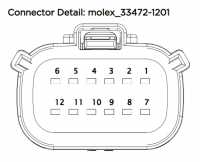
The battery heater itself does not have any onboard control circuitry, however, it is controlled by the Model S front HVJB using PWM on the HV cables. For this reason, if you want to easily control the battery heater, a front HVJB is required. As mentioned in the Tesla Model S Front HVJB article, the control pins are on the Molex MX 150 plug found on this unit. The LV connector on the bottom left side is a 12-pin Molex MX150 series (Molex p/n: 33472-1201). Only 6 of the 12 pins are populated, as follows:
| pin | function |
|---|---|
| 4 | 12V |
| 5 | PWM in |
| 6 | STATUS out |
| 10 | GND |
| 11 | HVIL in (not needed) |
| 12 | HVIL out (not needed) |
Control is done by applying a 12V PWM signal on pin 5 (PWM in). Note this must be a signal in the 12V range, a 5V PWM signal had no effect. Experimentally, some measure of control has been achieved at a frequency of 50Hz and two different ranges of duty cycle. From 20-30% duty cycle, the current increases fairly linearly though the minimum (20%) still draws a bit of power. However, from 30-40% the current decreases to nearly the same level as 20% duty cycle, but you are able to continue further, all the way to 45%, where the current decreases to the point where the heater draws very little power. Ultimately, not sure how useful this finding will be, but it's here for reference. The duty cycle for my (dlud) fhvjb was different. At 20-30% duty cycle no power was delivered to the heater. At 46% power was received and was maximum at 65%. Above 65% the power decreased. This was using a 50hz frequency.
As noted, HVIL pins 11 & 12 seem to have no effect on the function of the HVJB and can be left de-pinned.
Also, there does seem to be a feedback of a some sort on pin 6 (STATUS out), but not much as been done to interpret the data beyond noting it's a 5V square wave.
