BMW I3 Fast Charging LIM Module
The BMW LIM module is a CCS, CHAdeMO and AC charging controller. It is used to communicate between the vehicle and the public charging infrastructure, to allow fast charging to occur.
As these can be found affordably on eBay and from auto wreckers, they have been pursued as an open-source charger-interface project.
External links
github.com/damienmaguire/BMW-i3-CCS
> CAN logs
Design Guide for Combined Charging System (2015)
LIM versions
Only AC_DCO versions work for CCS. (Check if you have a MAC address on the label!)
| SN | IEC 61851
J1772 (AC) |
DIN 70121 | ISO 15118 | ISO 15118-20 | Cars | Used until | Tested |
|---|---|---|---|---|---|---|---|
| 61 35 9 346 827 | x | x | BMW i3 | ||||
| 61 35 9 346 820 | x | x | BMW i3 | ||||
| 61 35 9 353 646 | x | x | BMW i3 | Jul 2014 | x | ||
| 61 35 9 380 352 | x | x | ? | BMW i3 | Nov 2015 | ||
| 61 35 6 805 847 | x | x | ? | BMW i3 | Jul 2016 | ||
| 61 35 9 494 498 | x | x | ? | BMW i3 | 2018? | x | |
| 61 35 9 470 199 | x | x | ? | BMW i3 | ? | ||
| 61 35 9 454 319 | x | x | x | ? | BMW i3
Mini cooper SE |
now |
The LIM's are available new from BMW spare parts suppliers for € 240 but there might be some programming/codeing necessary before the unit behaves like the ones used during development of the solution.
Power Limits
The limits for pre 2017/26 (Week 26 of 2017) are 0V-500V 0A-250A, post 2017/27 (Week 27 of 2017) 0V-1000V -500A-+500A.
This probably indicates when they moved from DIN 70121 only to ISO 15118.
Connectors and Pinouts
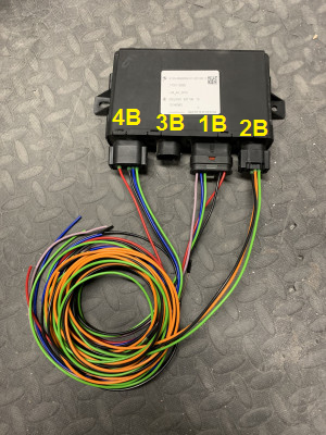
All connectors are available at https://www.auto-click.co.uk/ worldwide.
| Label | Description | Compatible Plugs |
|---|---|---|
| 4B | 12 Pin Connector | BMW 61138373632
Audi 4E0 972 713 TE 1534152-1 / 1534151-1 |
| 3B | 8 Pin Connector (CHAdeMO models only) | BMW 61138364624
Audi 4F0 972 708 TE 1-1534229-1 |
| 1B | 16 Pin Connector | Hirschmann 805-587-545 |
| 2B | 6 Pin Connector | BMW 61138383300
Audi 7M0 973 119 TE 1-967616-1 |
| X | Replacement Pins | 5-962885-1 |
| X | Rubber Seal | 1-967067-1 |

| Pin # | Function | Description |
|---|---|---|
| 1B-1 | - | |
| 1B-2 | - | |
| 1B-3 | LED_M | Lighting Charge Socket? (Not necessary) |
| 1B-4 | LOCK_MOT+ | Charge Inlet Lock Motor |
| 1B-5 | LOCK_MOT- | Charge Inlet Lock Motor |
| 1B-6 | CAN_H | Powertrain CAN |
| 1B-7 | CAN_L | Powertrain CAN |
| 1B-8 | IGN | Wake up signal +12V (ignition, contact 15) |
| 1B-9 | VCC | Constant Power +12V |
| 1B-10 | GND | Ground |
| 1B-11 | - | |
| 1B-12 | - | |
| 1B-13 | - | |
| 1B-14 | - | Internally connected to GND |
| 1B-15 | CHARGE_E | Goes to KLE. Guessing this is charge enable or drive interlock signal? |
| 1B-16 | LOCK_FB | Charge Inlet Lock Feedback (1k unlocked, 11k locked) |
| Pin # | Function | Description |
|---|---|---|
| 2B-1 | CP | Pilot (Charge Inlet) |
| 2B-2 | PP | Proxy (Charge Inlet) |
| 2B-3 | Jumper | Connected to Pin 4 |
| 2B-4 | Jumper | Connected to Pin 3 |
| 2B-5 | GND | Ground (Charge Inlet) |
| 2B-6 | US CCS1 version connected to 2B-2 |
3B Pinout:
- N/A (for CHAdeMO only)
| Pin # | Function | Description |
|---|---|---|
| 4B-1 | POS_CONT+ | Positive HV Contactor Control (Contactor coil resistance needs to be ~15 ohms) |
| 4B-2 | NEG_CONT+ | Negative HV Contactor Control |
| 4B-3 | POS_CONT- | Positive HV Contactor Control |
| 4B-4 | NEG_CONT- | Negative HV Contactor Control |
| 4B-5 | U_HV_DC | Charge Inlet DC Voltage (current input 3-20mA?) |
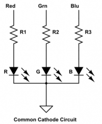
| 4B-6 | LED_RT | Red charge Status Light (12V RGB LED) |
| 4B-7 | LED_GN | Green charge Status Light (12V RGB LED) |
| 4B-8 | LED_BL | Blue charge Status Light (12V RGB LED) |
| 4B-9 | LED_GND | Charge Status Light Ground (common cathode of RGB LED) |
| 4B-10 | COV_MOT- | Charge Inlet Cover Motor (Not necessary) |
| 4B-11 | COV_MOT+ | Charge Inlet Cover Motor (Not necessary) |
| 4B-12 | COV_FB | Charge Inlet Cover Feedback (connect to GND to simulate open cover) |
Connector for BMW i3 CCS plug locking actuator is BMW part number 12527549033. Pins and seals should be the same as used on the LIM module.
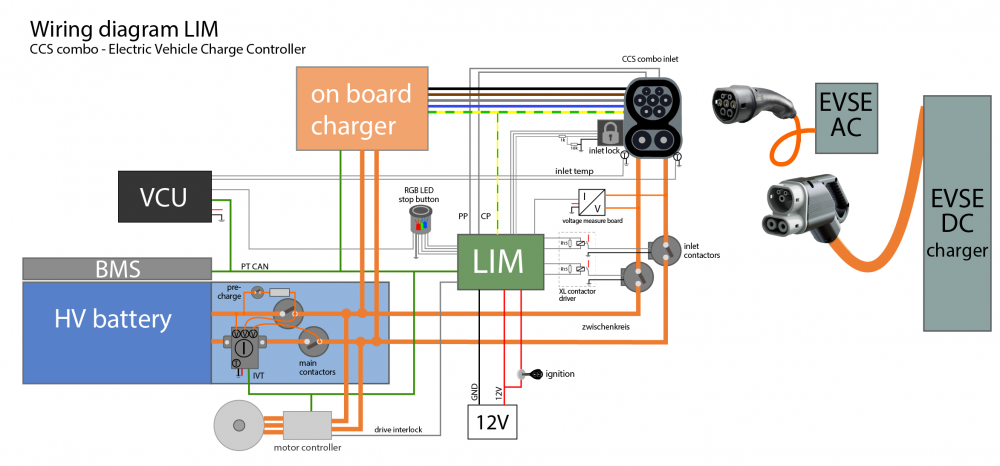
Wiring Diagram
CAN communication
A DBC CAN database file can be found here: I3 LIM CAN dbc1
This list has to be cleaned up once we know which messages are actually necessary for the LIM.
| ID | Function | sent by | interval | Notes |
|---|---|---|---|---|
| 0x112 | BMS msg. | VCU | 10ms | could also be sent by BMS |
| 0x12F | Wake up | VCU | 100ms | |
| 0x1A1 | Vehicle speed | VCU | 20ms | |
| 0x3E9 | Main LIM control | VCU | 200ms | |
| 0x431 | Battery info | VCU | 200ms | needed but does not control anything |
| 0x03C | Vehicle status | VCU | 200ms | |
| 0x2A0 | Central locking | VCU | 200ms | |
| 0x397 | OBD | VCU | 200ms | |
| 0x3F9 | Engine info | VCU | 200ms | Rex? |
| 0x3A0 | Vehicle condition | VCU | 200ms | |
| 0x330 | Range info | VCU | 200ms | |
| 0x432 | BMS SoC | VCU | 200ms | |
| 0x51A | Network management | VCU | 200ms | |
| 0x540 | Network management 2 | VCU | 200ms | |
| 0x512 | Network management edme | VCU | 200ms | |
| 0x560 | Network management kombi | VCU | 200ms | |
| 0x510 | Network management zgw | VCU | 200ms | |
| 0x328 | Counter | VCU | 1s | |
| 0x3E8 | OBD reset | VCU | 1s | |
| 0x2F1 | Lim DC charge command 2. | VCU | 100ms | |
| 0x2FA | Lim DC charge command 3. | VCU | 1s | |
| 0x2FC | Charge flap control | VCU | 100ms | |
| Messages sent by LIM | ||||
| 0x29E | CCS charger specs | LIM | ||
| 0x2EF | Min available voltage from the ccs charger. | LIM | ||
| 0x2B2 | Current and Votage as measured by the ccs charger | LIM | ||
| 0x3B4 | EVSE info CP, PP & inlet voltage | LIM | ||
| 0x272 | CCS contactor state and charge flap open/close status. | LIM | ||
| 0x337 | Inlet lock status | LIM | ||
LIM peripherals
Isolated DC charge inlet voltage sense board
The LIM gets the inlet DC voltage from a board in the KLE.
This board needs to produce an isolated 3-20mA current signal from the high voltage DC voltage.
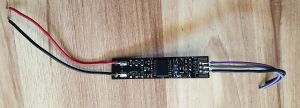
The circuit of the voltage sense board is shared here https://openinverter.org/forum/viewtopic.php?p=28143#p28143
Large fast charge contactor control
The LIM produces a 12V, 50% PWM on the positive and negative fast charging contactor outputs and measures the current draw of the contactors.
This makes it a bit harder to use different contactors.
The easiest option is to place a 15 ohms resistor (with heat sink) in parallel to simulate the original contactor coil and a small relais to drive the large Gigavac contactor with internal PWM economizer or dual coil.
Each of the two 15 ohm resistor has to dissipate ~6W @ 13.4V, 50% PWM.
Further investigation is needed to find out if the LIM also detects a contactor failure from the current draw.

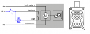
Inlet lock feedback

The i3 uses a quite expensive Phoenix CCS inlet and it would be nice to be able to use the cheaper Duosida CCS inlets.
The charge inlet lock should work with the Duosida lock as well but the feedback (1k unlocked, 11k locked) is a bit different which requires some additional resistors.
RGB charge indication light
The RGB charge indicator LED should have a common cathode and series resistors for 12V DC.
Nice push buttons with integrated RGB led are available on Aliexpress for a few dollars.
The switch signal is useful to stop charging and has to be connected to the ECU. The ECU then terminates the charging process over the CAN bus.
Charge control
The EVSE (charging station) shares it’s limits with PWM during AC charging or PLC during CCS sessions but often the car can not handle the max available power of the charging station.
The actual battery voltage and battery current is needed by the LIM to check the proper working of the charging station. In this setup the battery voltage and current gets measured by a Isabellenhütte IVT CAN bus sensor but those values could also be measured and shard on the CAN bus by the BMS. (message 0x112)
Battery dependant charging current control
During (fast) charging a cell voltage and cell temperature dependant current limit is very important.
The BMS or VCU should limit this value according to the battery specifications and protect the cells from damage and ageing at all times.
CCS inlet temperature sensors
Many CCS inlets have DC contact temperature sensors for safety. The LIM has no temperature sensor inputs but the VCU could be connected to the sensors (usually PT1000 or NTC) and reduce charging speed if the inlet gets too hot.
On board charger control
The LIM shares PP (charging cable) and CP (charging station) AC current limits in the 0x3B4 EVSE info CAN message.
If the on board charger accepts a AC current limit this value can be directly used but some chargers can only be controlled with DC current commands.
Since we don't know the actual AC current we can only estimate it with a fixed AC voltage, efficiency...
DC_current = fixed_AC_voltage * CP_PP_current_limit * phase_count * charger_efficiency / DC_voltage
CCS charging sequence
This document actually covers Fast and Smart Charging Solutions for Full Size Urban Heavy Duty Applications but since most of the protocols used are similar it has comparable sequence diagrams with description for normal start up, normal shutdown, DC supply initiated emergency stop and EV initiated emergency stop.
https://assured-project.eu/storage/files/assured-10-interoperability-reference.pdf
LIM logs
Here you can find some CAN logs of AC and DC charging sessions. https://github.com/damienmaguire/BMW-i3-CCS/tree/main/CAN_Logs
QCA7005 SPI captures on Damien's GitHub https://github.com/damienmaguire/BMW-i3-CCS/tree/main/SPI_Caps
Observations
VIN Numbers is not required for AC or DC fast charging to function
Functional LIMs have come from vehicles where the Air Bags have deployed, indicating that the module still works after a "Safety" event has occurred.
LIM board components
| Chip | Description | Function | Datasheet |
|---|---|---|---|
| Renesas V850E2/FG4 | 32-bit Single-Chip Microcontroller | main MCU | https://www.renesas.com/us/en/document/dst/data-sheet-v850e2fg4 |
| Qualcomm QCA7000 | HomePlug® Green PHY, single chip solution | PLC Green PHY | https://openinverter.org/forum/download/file.php?id=9611 |
| Infineon TLE 7263E | Integrated HS-CAN, LIN, LDO and HS Switch, System Basis Chip | CAN, 2xLDO, wake-up | https://docs.rs-online.com/db13/0900766b814d680b.pdf |
| TI SN74LVC2T45-Q1 | Dual-Bit Dual Supply Transceiver with Configurable Voltage Translation | https://www.ti.com/lit/gpn/sn74lvc2t45-q1 | |
| NXP 74LVC1T45 | Dual supply translating transceiver | https://datasheetspdf.com/pdf-file/648034/NXP/74LVC1T45/1 | |
| STM L9951XP | Actuator driver | inlet lock motor | https://www.st.com/resource/en/datasheet/l9951.pdf |
| STM TS321 | Low-Power Single Operational Amplifier | https://www.ti.com/lit/gpn/ts321 | |
| TI LM2902 | Quadruple general-purpose operational amplifier | https://www.ti.com/lit/gpn/lm2902 | |
| STM VNQ5E250AJ-E | Quad channel high-side driver with analog current sense | LEDs?, contactors? | https://www.st.com/resource/en/datasheet/vnq5e250aj-e.pdf |