Tesla Model 3 Drive Unit PCB: Difference between revisions
No edit summary |
No edit summary |
||
| Line 1: | Line 1: | ||
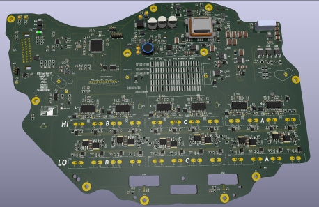
Open Source logic board for the Tesla Model 3 rear drive unit. Based on the inverter designed by Johannes Heubner using FOC control. | Open Source logic board for the Tesla Model 3 rear drive unit. Based on the inverter designed by Johannes Heubner using FOC control. | ||
[[File:M3driver.png|thumb|458x458px|m3 inverter replacement pcb]] | [[File:M3driver.png|thumb|458x458px|m3 inverter replacement pcb]] | ||
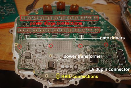
[[File: | [[File:M3inverter-parts.jpg|thumb|454x454px|parts/ connections to salvage/ unsolder]] | ||
Latest revision as of 20:48, 18 November 2025
Open Source logic board for the Tesla Model 3 rear drive unit. Based on the inverter designed by Johannes Heubner using FOC control.


the model 3 drive unit inverters feature a PCB with both HV and LV circuits, the gate drivers, and logic. thus a simple replacement brain board is not possible. canbus control is complicated and requires use of tesla's diagnostics software for inverter pairing. this is a legal greyzone and not a fully opensource option. Instead a full fledged replacement board with gate drivers was designed to allow full lobotomization of elon, thus gaining full opensource control of the model 3/y drive units!
https://github.com/damienmaguire/Tesla-Model-3-Drive-Unit
https://github.com/davefiddes/stm32-sine
https://www.evbmw.com/index.php/evbmw-webshop/tesla-boards/tesla-model-3-du-beta
parts needed to be fitted:
-current sensors: MLX91209LVA-CAA-002-SP (can be sourced from original board)
-gate drivers: STGAP1BSTR (can be sourced from original board)
-power transformer: VGT22EPC-200S6A12 (can be sourced from original board)
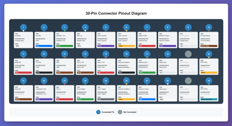
-(for wiring harness) 30 pin matting connector: Sumitomo Original 6189-6987 61896987 https://www.aliexpress.com/item/1005005920568514.html
-30 pin connector and pins are a private stocked part, so must be salvaged from the original board
-11x torx T20 screws holding the board onto the case
-3x T10 securing the current sensor trim to the pcb
OR
- 2x T10 screws holding the pryofuse and current sensor trim
