Honda Accelerator pedal sensor: Difference between revisions
Jump to navigation
Jump to search
→General Information: Added dimensioned photos. |
Added link to 3D scan |
||
| Line 64: | Line 64: | ||
[[File:With cover and bracket.jpg|none|thumb|With cover and bracket, P/N 37971-RCA-A01 (Honda Element)]] | [[File:With cover and bracket.jpg|none|thumb|With cover and bracket, P/N 37971-RCA-A01 (Honda Element)]] | ||
[https://grabcad.com/library/honda-accelerator-pedal-sensor-scan-1 3D scan of bracket, sensor, and cover] | |||
= References = | |||
<references /> | <references /> | ||
[[Category:Honda]] | [[Category:Honda]] | ||
[[Category:Accelerator pedals and position sensors]] | [[Category:Accelerator pedals and position sensors]] | ||
Revision as of 05:11, 20 January 2025
General Information
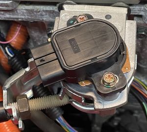
The original cable is shielded to avoid interference from other sources and resulting unwanted acceleration or deceleration.

The voltage from both sensors ramps linearly from the fully released position to the fully depressed position[2]. The pedal should be supplied with a reasonable stable and accurate 5V supply to ensure a proper readout.
| Pedal Position | Sensor 1 | Sensor 2 |
|---|---|---|
| Fully Released | 0.05 V | 4.30 V |
| Fully Depressed | 0.10 V | 4.90 V |
Versions
| Part Number | Cars Used In | Electrical Connector | Remarks |
|---|---|---|---|
|
|
|
Connector can be found on Aliexpress |
Photos
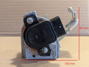
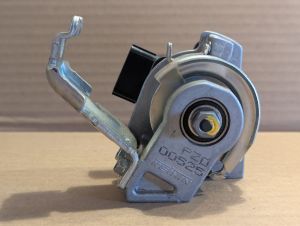
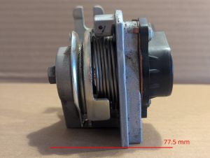
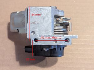
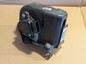
3D scan of bracket, sensor, and cover
References
- ↑ Forum Reference: https://openinverter.org/forum/viewtopic.php?p=66006#p66006
- ↑ Add reference