Volvo V60 Battery: Difference between revisions
Jump to navigation
Jump to search
No edit summary |
m Changed text to tables |
||
| Line 8: | Line 8: | ||
External connector (9 pin): | External connector (9 pin): | ||
{| class="wikitable" | |||
|+ | |||
!Pin | |||
!Function | |||
!Note | |||
|- | |||
|1 | |||
| +12V | |||
|Vehicle 12V, switched by the BMS master, not regulated | |||
|- | |||
|2 | |||
|CAN-L | |||
| | |||
|- | |||
|3 | |||
|CAN-H | |||
| | |||
|- | |||
|4 | |||
|Digital input | |||
|internally 50K pulled up | |||
|- | |||
|5 | |||
|GND | |||
|only first slave has this pin connected to the master, guess for some kind of 'first slave present' detection | |||
|- | |||
|6 | |||
|Digital output | |||
|open collector with 1K in series | |||
|- | |||
|7 | |||
|GND | |||
| | |||
|- | |||
|8 | |||
|CAN-L | |||
|parallel to pin-2 | |||
|- | |||
|9 | |||
|CAN-H | |||
|parallel to pin-3 | |||
|} | |||
[[File:20250827 201254.jpg|thumb]] | [[File:20250827 201254.jpg|thumb]] | ||
Internal connector (14 pin): | Internal connector (14 pin): | ||
[[File:20250827 201444.jpg|thumb]] | [[File:20250827 201444.jpg|thumb]] | ||
Pin 1 | {| class="wikitable" | ||
|+ | |||
!Pin | |||
!Function | |||
!Note | |||
|- | |||
|1 | |||
|Cell 1 positive | |||
| | |||
|- | |||
|2 | |||
|Cell 1 negative | |||
|connected to main negative terminal | |||
|- | |||
|3 | |||
|Cell 1 negative | |||
|connected to main negative terminal | |||
|- | |||
|4 | |||
|NC | |||
|not connected | |||
|- | |||
|5 | |||
|Cell 10 positive | |||
|connected to main positive terminal | |||
|- | |||
|6 | |||
|Cell 10 positive | |||
|connected to main positive terminal | |||
|- | |||
|7 | |||
|Cell 9 positive | |||
| | |||
|- | |||
|8 | |||
|Cell 2 positive | |||
| | |||
|- | |||
|9 | |||
|Cell 3 positive | |||
| | |||
|- | |||
|10 | |||
|Cell 4 positive | |||
| | |||
|- | |||
|11 | |||
|Cell 5 positive | |||
| | |||
|- | |||
|12 | |||
|Cell 6 positive | |||
| | |||
|- | |||
|13 | |||
|Cell 7 positive | |||
| | |||
|- | |||
|14 | |||
|Cell 8 positive | |||
| | |||
|} | |||
[https://openinverter.org/forum/viewtopic.php?t=885 Forum topic on the Volvo V60 battery pack] | [https://openinverter.org/forum/viewtopic.php?t=885 Forum topic on the Volvo V60 battery pack] | ||
Revision as of 19:27, 27 August 2025

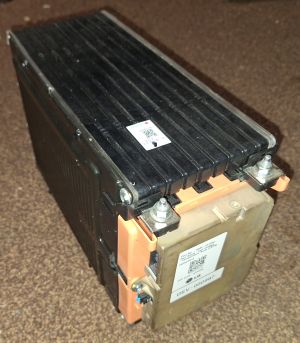
The Pack in the Volvo V60 D6 consists of 10 modules each made up of 10 cells. The cells are Li_ion pouch cells with a capacity of 32.5Ah. Making the modules 37V with a capacity of 1.2kWh
The BMS satellite module: LG calls them "Cell Voltage Temperature Node (CVTN).
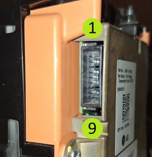
External connector (9 pin):
| Pin | Function | Note |
|---|---|---|
| 1 | +12V | Vehicle 12V, switched by the BMS master, not regulated |
| 2 | CAN-L | |
| 3 | CAN-H | |
| 4 | Digital input | internally 50K pulled up |
| 5 | GND | only first slave has this pin connected to the master, guess for some kind of 'first slave present' detection |
| 6 | Digital output | open collector with 1K in series |
| 7 | GND | |
| 8 | CAN-L | parallel to pin-2 |
| 9 | CAN-H | parallel to pin-3 |

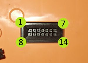
Internal connector (14 pin):

| Pin | Function | Note |
|---|---|---|
| 1 | Cell 1 positive | |
| 2 | Cell 1 negative | connected to main negative terminal |
| 3 | Cell 1 negative | connected to main negative terminal |
| 4 | NC | not connected |
| 5 | Cell 10 positive | connected to main positive terminal |
| 6 | Cell 10 positive | connected to main positive terminal |
| 7 | Cell 9 positive | |
| 8 | Cell 2 positive | |
| 9 | Cell 3 positive | |
| 10 | Cell 4 positive | |
| 11 | Cell 5 positive | |
| 12 | Cell 6 positive | |
| 13 | Cell 7 positive | |
| 14 | Cell 8 positive |