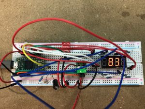
State of Charge meter using a Teensy 4.0

This is a CAN bus state-of-charge meter based on a Teensy 4.0. Teensy's aren't the cheapest boards (an STM32 is a tenth of the price), but they are tiny, have on-board CAN and are very easy to develop for.
It displays a state-of-charge or voltage value according the integer number sent over CAN bus to the configured address(es)
SoC values between 0 and 1000 will be displayed as " 0.0" to "100 ". The display flashes " 0.0" when it reaches zero. Anything else (or no data) will be displayed as "----"
Voltage values between 1 and 999 will be displayed as " 1V" to "999V ". Anything else (or no data) will be displayed as "---V"
A touch sensor allows you to toggle the display between SoC and voltage.
It includes automatic night time dimming.
Component list
- Teensy 4.0 board
- SN65HVD230-based CAN transceiver
- 3461BS-1 4 digit common anode 7 segment display
- 8x 220R resistors
- Photocell
- 10k resistor
- 47uF capacitor
- TTP223 Capacitive Touch Switch
Wiring

Follow the Teensy 4.0 connection schematic
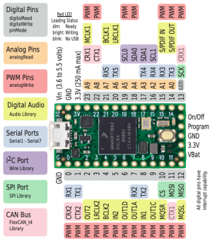
- Connect the CAN transceiver to Teensy 3.3V, GND, CRX2 and CTX2
- Connect the LED D1, D2, D3 and D4 digit pins to Teensy 5, 4, 3, 2
- Connect the LED a, b, c, d, e, f, g and DP segments to Teensy 16, 17, 18, 19, 20, 21, 22, 23 via 220R resistors
- Connect the Photocell to Teensy 3.3V and A0. Connect A0 to GND via a 10k resistor and 47uF capacitor in parallel.
- Connect the Touch Switch to Teensy 3.3V, GND and 15
You'll need suitable 12V -> 5V power supply for automotive use. For development, it'll work fine off 5V USB.
Code
Fire up Teensyduino.
Install the FlexCAN_T4 library
Paste in the following code:
// CAN bus state-of-charge meter for Teensy 4.x and 4-digit 7-segment display
// Includes automatic LED brightness control
//
// Usage: send integer number over CAN bus to configured address
// SoC values between 0 and 1000 will be displayed as "  0.0" to "100 "
// The display flashes "  0.0" when it reaches zero
// Anything else (or no data) will be displayed as "----"
// Voltage values between 1 and 999 will be displayed as "  1V" to "999V "
// Anything else (or no data) will be displayed as "---V"
// Touch selection to toggle display between SoC and  voltage
//
// electric_dart 2021

// define display
// values below are for 3461BS-1 4 digit common anode 7 segment display
const int ledDigits = 4; // 4 digits
const int ledSegments = 7; // 7 segments
const int pinSegment[ledSegments] = {16, 17, 18, 19, 20, 21, 22}; // pins for a,b,c,d,e,f,g segments
const int pinDecimalPoint = 23; // pin for decimal point
const int pinDigit[ledDigits] = {5, 4, 3, 2}; // common digit pins, left to right
const boolean ledIsCommonAnode = 1; // 1=common anode 0=common cathode
const int ledRefreshHz = 100; // minimum 50Hz to avoid flicker
const int ledFlashHz = 2; // for flashing display

// define display characters
const int zero[ledSegments] = {HIGH, HIGH, HIGH, HIGH, HIGH, HIGH, LOW};
const int one[ledSegments] = {LOW, HIGH, HIGH, LOW, LOW, LOW, LOW};
const int two[ledSegments] = {HIGH, HIGH, LOW, HIGH, HIGH, LOW, HIGH};
const int three[ledSegments] = {HIGH, HIGH, HIGH, HIGH, LOW, LOW, HIGH};
const int four[ledSegments] = {LOW, HIGH, HIGH, LOW, LOW, HIGH, HIGH};
const int five[ledSegments] = {HIGH, LOW, HIGH, HIGH, LOW, HIGH, HIGH};
const int six[ledSegments] = {HIGH, LOW, HIGH, HIGH, HIGH, HIGH, HIGH};
const int seven[ledSegments] = {HIGH, HIGH, HIGH, LOW, LOW, LOW, LOW};
const int eight[ledSegments] = {HIGH, HIGH, HIGH, HIGH, HIGH, HIGH, HIGH};
const int nine[ledSegments] = {HIGH, HIGH, HIGH, LOW, LOW, HIGH, HIGH};
const int blank[ledSegments] = {LOW, LOW, LOW, LOW, LOW, LOW, LOW};
const int dash[ledSegments] = {LOW, LOW, LOW, LOW, LOW, LOW, HIGH};
const int volt[ledSegments] = {LOW, LOW, HIGH, HIGH, HIGH, LOW, LOW};
// add additional characters here if required
const int* character[13] = {zero, one, two, three, four, five, six, seven, eight, nine, blank, dash, volt};

// photocell parameters
int pinPhotocell = 14; // photocell pin
int photocellDark = 500; // adjust dark level for your photocell
int photocellLight = 1000; // adjust light level for your photocell

// touch parameters
int pinOnboardLED = 13;
int pinTouch = 15;
int touchCurrentState;
int touchLastState;

// CAN bus setup
const long canIDsoc = 0x350; // set this to match your SoC CAN bus ID
const long canIDvoltage = 0x522; // set this to match your voltage CAN bus ID
const long canSpeed = 500000; // set this to match your CAN bus speed
const long canTimeout = 10; // seconds to wait without data before showing error
#include <FlexCAN_T4.h>
FlexCAN_T4<CAN2, RX_SIZE_256, TX_SIZE_16> Can0; // Using CAN2 on pins 0 & 1

// internal variables
int ledRefreshMilliseconds = 1000 / (ledDigits * ledRefreshHz); // milliseconds
int ledOnMicroseconds; // microseconds
unsigned long nowMilliseconds;
unsigned long nowMicroseconds;
unsigned long nextRefreshMilliseconds = 0;
unsigned long nextBlankMicroseconds = 0;
unsigned long nextTimeoutMilliseconds = 0;
unsigned long nextFlashMilliseconds = 0;
boolean ledFlashState = 1;
int digitSelect = 0;
int readingSoC = -1;
int readingVoltage = -1;
int photocellReading;
int ledBrightness; // score 1 to 10
int displayMode = 0; // 0=SoC, 1=Voltage

void clearDisplay()
{
  for (int i = 0; i < ledDigits; ++i)
  {
    digitalWrite(pinDigit[i], HIGH ^ ledIsCommonAnode);
  }
}

void writeDisplayDigit(int digit, int value, boolean decimal)
// digit: numbered left-to-right, beginning at zero
// value: the character to display from character[] array
// decimal: set this to 1 to switch the decimal point on
{
  for (int i = 0; i < ledSegments; ++i)
  {
    digitalWrite(pinSegment[i], character[value][i] ^ ledIsCommonAnode);
  }
  digitalWrite(pinDecimalPoint, decimal ^ ledIsCommonAnode);
  digitalWrite(pinDigit[digit], LOW ^ ledIsCommonAnode);
}

void writeDisplaySoC(int digit, int value) // customise this section according to what you want to display
{
  if (value == 1000) { // display "100 " if the input value is 1000
    switch (digit) {
      case 0:
        writeDisplayDigit(0, 1, 0);
        break;
      case 1:
        writeDisplayDigit(1, 0, 0);
        break;
      case 2:
        writeDisplayDigit(2, 0, 0);
        break;
    }
  }
  else if (value >= 100 and value < 1000) { // display " 99 " to " 10 " for input values from 999 to 100
    switch (digit) {
      case 1:
        writeDisplayDigit(1, value / 100, 0);
        break;
      case 2:
        writeDisplayDigit(2, (value / 10) % 10, 0);
        break;
    }
  }
  else if (value >= 1 and value < 100) { // display "  9.9" to "  0.1" for input values from 99 to 1
    switch (digit) {
      case 2:
        writeDisplayDigit(2, value / 10, 1);
        break;
      case 3:
        writeDisplayDigit(3, value % 10, 0);
        break;
    }
  }
  else if (value == 0) { // display flashing "  0.0" for input value 0
    if (nowMilliseconds > nextFlashMilliseconds) {
      nextFlashMilliseconds = nowMilliseconds + ( 1000 / ledFlashHz );
      ledFlashState = ledFlashState ^ 1;
    }
    if (ledFlashState == 1) {
      switch (digit) {
        case 2:
          writeDisplayDigit(2, 0, 1);
          break;
        case 3:
          writeDisplayDigit(3, 0, 0);
          break;
      }
    }
    else {
      switch (digit) {
        case 2:
          writeDisplayDigit(2, 10, 1);
          break;
        case 3:
          writeDisplayDigit(3, 10, 0);
          break;
      }
    }
  }
  else { // display "----" for anything else
    writeDisplayDigit(digit, 11, 0);
  }
}

void writeDisplayVoltage(int digit, int value) // customise this section according to what you want to display
{
  if (value >= 100 and value < 1000) { // display "100V" to "999V" for input values 100 to 999
    switch (digit) {
      case 0:
        writeDisplayDigit(0, (value / 100) % 10, 0);
        break;
      case 1:
        writeDisplayDigit(1, (value / 10) % 10, 0);
        break;
      case 2:
        writeDisplayDigit(2, value  % 10 , 0);
        break;
      case 3:
        writeDisplayDigit(3, 12, 0);
        break;
    }
  }
  else if (value >= 10 and value < 100) { // display " 10V" to " 99V " for input values from 10 to 99
    switch (digit) {
      case 1:
        writeDisplayDigit(1, value / 10, 0);
        break;
      case 2:
        writeDisplayDigit(2, value % 10, 0);
        break;
      case 3:
        writeDisplayDigit(3, 12, 0);
        break;
    }
  }
  else if (value >= 1 and value < 10) { // display "  1V" to "  9V " for input values from 1 to 9
    switch (digit) {
      case 2:
        writeDisplayDigit(2, value % 10, 0);
        break;
      case 3:
        writeDisplayDigit(3, 12, 0);
        break;
    }
  }
  else { // display "---V" for anything else
    switch (digit) {
      case 0:
        writeDisplayDigit(0, 11, 0);
        break;
      case 1:
        writeDisplayDigit(1, 11, 0);
        break;
      case 2:
        writeDisplayDigit(2, 11, 0);
        break;
      case 3:
        writeDisplayDigit(3, 12, 0);
        break;
    }
  }
}


void setup() {
  Serial.begin(9600); //initialise serial communications at 9600 bps

  // Initialise CAN bus
  delay(1000); // allow CAN hardware to stabilise
  Can0.begin();
  Can0.setBaudRate(canSpeed);
  Can0.setMaxMB(16);
  Can0.enableFIFO();
  Can0.enableFIFOInterrupt();
  Can0.onReceive(canDataReceived);
  Can0.mailboxStatus();

  // Initialise LED display

  // segement pins
  for (int i = 0; i < ledSegments; ++i)
  {
    pinMode(pinSegment[i], OUTPUT);
  }

  // decimal point pin
  pinMode(pinDecimalPoint, OUTPUT);

  // digit pins
  for (int i = 0; i < ledDigits; ++i)
  {
    pinMode(pinDigit[i], OUTPUT);
  }
  clearDisplay();

  pinMode(pinOnboardLED, OUTPUT);
  pinMode(pinPhotocell, INPUT);
  pinMode(pinTouch, INPUT);
  touchCurrentState = digitalRead(pinTouch);

}

void canDataReceived(const CAN_message_t &msg) {
//  Serial.print("MB "); Serial.print(msg.mb);
//  Serial.print("  OVERRUN: "); Serial.print(msg.flags.overrun);
//  Serial.print("  LEN: "); Serial.print(msg.len);
//  Serial.print(" EXT: "); Serial.print(msg.flags.extended);
//  Serial.print(" TS: "); Serial.print(msg.timestamp);
//  Serial.print(" ID: "); Serial.print(msg.id, HEX);
//  Serial.print(" Buffer: ");
//  for ( uint8_t i = 0; i < msg.len; i++ ) {
//    Serial.print(msg.buf[i], HEX); Serial.print(" ");
//  } Serial.println();

  switch (displayMode) { // according to display mode
    case 1:
      if (msg.id == canIDvoltage) {
      // Matching voltage CAN bus frame arrived!
        //readingVoltage = (msg.buf[2] << 24) | (msg.buf[3] << 16) | (msg.buf[4] << 8) | (msg.buf[5]);   // now piece it together
        readingVoltage = (msg.buf[6] << 8) | (msg.buf[7]);   // now piece it together
        nextTimeoutMilliseconds = nowMilliseconds + (canTimeout * 1000); // set next timeout
      }
      break;
    default:
      if (msg.id == canIDsoc) {
      // Matching SoC CAN bus frame arrived!
        readingSoC = (msg.buf[6] << 8) | (msg.buf[7]);   // now piece it together
        nextTimeoutMilliseconds = nowMilliseconds + (canTimeout * 1000); // set next timeout
      }
      break;
  }
}

void loop() {

  // add extra code here

  // pot input for testing without CAN bus
  //reading = analogRead(pin_pot);
  //reading = map(reading, 10, 1023, 0, 1000);

  touchLastState = touchCurrentState;
  touchCurrentState = digitalRead(pinTouch);
  if(touchLastState == LOW && touchCurrentState == HIGH) {
    // toggle display
    displayMode = !displayMode;
    // control LED arccoding to the toggled state
    digitalWrite(pinOnboardLED, displayMode);
  }
  //
  //

  Can0.events();

  // take a timestamp
  nowMilliseconds = millis();
  nowMicroseconds = micros();

  // calculate required LED brightness score (1-10) and set time to remain on (in microseconds) as a proportion of the refresh interval
  photocellReading = analogRead(pinPhotocell);
  photocellReading = constrain(photocellReading, photocellDark, photocellLight);
  ledBrightness = map(photocellReading, photocellDark, photocellLight, 1, 10);
  ledOnMicroseconds = ledBrightness * ledRefreshMilliseconds * 100; // microseconds

  // timeout if no data received
  if (nowMilliseconds > nextTimeoutMilliseconds) {
    readingSoC = -1; // display "----"
    readingVoltage = -1; // display "----"
  }

  // is it time to refresh display?
  if (nowMilliseconds > nextRefreshMilliseconds) {
    nextRefreshMilliseconds = nowMilliseconds + ledRefreshMilliseconds; // set the time in milliseconds for the next refresh
    nextBlankMicroseconds = nowMicroseconds + ledOnMicroseconds; // set the time in microseconds for LEDs to remain on (for dimming)
    // multiplexed display, so enable one digit at at time
    switch (displayMode) { // according to display mode
      case 1:
        writeDisplayVoltage(digitSelect, readingVoltage);
        break;
      default:
        writeDisplaySoC(digitSelect, readingSoC);
        break;
    }
    ++digitSelect; // we'll do the next digit on the next pass
    if (digitSelect > ledDigits - 1 ) { // all digits done?
      digitSelect = 0;  // wrap around to first digit again.
    }
  }

  // is it time to switch the LEDs off?
  if (nowMicroseconds > nextBlankMicroseconds ) {
    clearDisplay();
  }
}
Try it out!
Compile and upload the code to your Teensy board. The code isn't very complicated, so I set mine to run at 150MHz.
If you send CAN data to the specified node ID, the display should spring into life.
<YouTube></nowiki>https://youtu.be/s-Gadj3Rnxw<nowiki></youtube>