Toyota Auris/Yaris Inverter
Th Auris/Yaris Inverter Board is an open source project to repurpose Toyota Auris/Yaris (and Prius C , Prius Aqua and Lexus CT200H) inverters for DIY EV use.
The inverters are nearly identical to Toyota Prius Gen 3 inverters, with a smaller format logic board to fit under a sloped casing. It is believed to have a smaller main capacitor and hence be of lower power capabilities [* Needs testing to confirm and adding here ]
They are inexpensive (<£100 in UK at the start of 2021) and suitable for a variety of EV / Charger and other inverter projects.
See these videos for a teardown, disassembly and explanation of the Gen3 Inverter:
https://www.youtube.com/watch?v=Pw3JqkI6VO4 (Teardown)
https://youtu.be/QBoRSXIwZQs (Regarding p0a94 error code for DC-DC Converter Performance)
The Project consists of a open inverter circuit board (adapted from Prius Gen3 board) and programming which replaces the OEM logic board in the Auris/Yaris inverter.
This allows independent control of mg1 power stage, mg2 power stage, buck/boost converter and the DC/DC converter.
Resources
Support thread is here : https://openinverter.org/forum/viewtopic.php?f=14&t=767
For using it as a charger , thread is here : https://openinverter.org/forum/viewtopic.php?f=14&t=825
Resources and design files on Github : https://github.com/damienmaguire/Yaris-Auris-Inverter
Available on the EVBMW.COM webshop : evbmw.com Yaris/Auris boards in partial built and full kit format.
There is a Auris/Yaris version of the dual motor board which allows both MG1 and MG2 of Toyota transmissions or (any 2 other suitable motors) to be powered by the same inverter, support thread here: https://openinverter.org/forum/viewtopic.php?f=14&t=1051
- Measurements of the Toyota Yaris Inverter
-
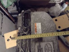 Depth
Depth -
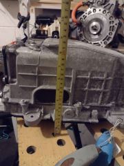 Height
 -
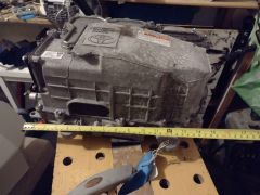 Width
Width -
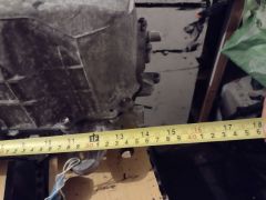 Detail of the Width


Timeline
17/05/20 : Prototype build commenced at JLCPCB.
28/06/20 : Block 2 boards with corrections to incorrect pinouts and component values now available from the evbmw webshop. https://www.evbmw.com/index.php/evbmw-w+...+-board-kit
24/09/20 Firmware now available to run the buck/boost module as an AC onboard charger: HERE: https://github.com/celeron55/prius3charger_buck
Schematic and pcb layout uploaded to github : https://github.com/damienmaguire/Yaris-Auris-Inverter
Design files available to Patrons only as of this date. https://www.patreon.com/evbmw
Schematic and pcb layout for Dual Motor boards on Github here : https://github.com/damienmaguire/Prius-Gen3-Inverter/tree/master/Small%20board%20V1d
Buildup and setup
Most of the build-up / setup is identical to the V1C Prius board here: Toyota Prius Gen3 Board
Video build tutorials here : https://www.youtube.com/watch?v=QE-zym8iIgM&t=439s ,here : https://www.youtube.com/watch?v=Nu5_OBOPk4s&t=319s and herehttps://www.youtube.com/watch?v=xoNs2NqjXd8
FOC Setup and tuning is as per Prius gen3 here : https://www.youtube.com/watch?v=tirDQJ6iH28&t=2306s
Also Note
But also note : (Source https://openinverter.org/forum/viewtopic.php?f=14&t=767 )
- On the Yaris boards (block111 and before) when using resolver you would need to remove the two pullups R30 and R29. See schematic :
https://raw.githubusercontent.com/damie+...+ematic.pdf
2. There is an error on early boards (block 111 and before) : MG1 resistor divider values are wrong. R41 and 42 should be 6k2 not 4k7 and R46 and R45 should be 3k6 not 4k7.
3. The MG2 current sensor socket has the pins reversed. this can be solved by cutting the socket to allow the plug in upside down or by cutting and resoldering the current sensor wires. Plugging them in will kill the -5v output of PS1 (a SGM3204 SOT if you live in china ) or a LM2776DBVT for europe. This is Block ii version and below.
4. Conn11 is the external hvil which is not used.
5. vcc+5v may be problematic , it may be at the limit of it's current due to use by Wifi and current sensors possibly causing a reduced Vcc 5v. try adding an external +5v line.. [ * needs confirming]