Page 1 of 2
Tesla Charger Support thread gen2/gen3
Posted: Wed Jan 31, 2024 12:32 pm
by janosch
Hello,
the last one got closed because it went out of hand, so here is a new one.
Helpful resources for both:
Wiki Gen2
Wiki Gen3
Tesla Charger Firmware thread
previous:
Tesla Charger Support Thread (started in 2019)
There has been ongoing development for a long time, so consider the information in above resources and:
Cross reference it with the date of it being published.
Also, Gen3 and Gen2 operate very similarly on a firmware level:
Even if you are using Gen3, the documentation to Gen2 might help you resolve your problem and vice versa.
Any other questions can be posted below, I am available for paid calls of course, but a lot of questions can be answered when reading above material, or posted here for free and me and others can chip in

Re: Tesla Charger Support thread gen2/gen3
Posted: Fri Apr 05, 2024 3:52 pm
by PetersonOctavius
Hi there,
as im waiting for my OI replacement board for the gen2 i was wondering if its possible to leave the battery pack permanently connected to the charger ( via a fuse) and the gen2 DCDC (via a fuse ).
thanks in advance
Re: Tesla Charger Support thread gen2/gen3
Posted: Sat Apr 06, 2024 6:03 pm
by arber333
Hi, i am installing Tesla Gen2 charger to my Mazda and i need to setup a disable circuit for VCU so that someone cant just drive off with charge cable connected
.
I am looking at schematic for both connectors and i notice there are two additional pins which are ready as input and output but dont seem to be used.
Those pins are OUT4 and IN2. Out4 is commanded through ULN2003 chip by D51 and IN2 is sensed through resistor divider by D7. Can someone explain the function of those pins and if they can be used in current firmware?
tnx
Re: Tesla Charger Support thread gen2/gen3
Posted: Thu May 09, 2024 12:14 pm
by medo
Is there a way to use the Tesla OBC Gen 3 for fast charging??
Re: Tesla Charger Support thread gen2/gen3
Posted: Sun May 19, 2024 8:49 am
by janosch
arber333 wrote: ↑Sat Apr 06, 2024 6:03 pm
Tesla Gen2 charger ... disable circuit
I listened in to CP & PP with a little circuit and when finding a resistance there the system knew an EVSE was plugged in and vehicle mustn't drive away. That worked for me. However, it might be even easier to use the pins that Damien left there for us.
The only reason I rolled my own circuit at the time was I didn't understand that the signals from the board are open drain.
https://openinverter.org/wiki/Tesla_Mod ... onnections
Discussion here:
viewtopic.php?p=46302#p46302
Relevant circuits here:
https://github.com/damienmaguire/Tesla- ... ematic.pdf
Re: Tesla Charger Support thread gen2/gen3
Posted: Sun May 19, 2024 11:39 am
by arber333
Thank you for the data and drawings.
I saw a strange behaviour with Tesla charger. Charger will pull EVSE in and start charging. All of a sudden charger will drop chage and reset. Happened multiple times now. Strange!!! I traced this to aux battery being lowish. Whenever car would stay in a garage long time this would happen and after resetting charge and harrowing clacking of the DC system in a while charging would begin. It seems Tesla gen2 charger circuit is sensitive to 12V input.
I made a simple test. I left the car for some time and then tried to charge. Yep it dropped out and reset.
Then i turned the car ON for some time so that DCDC would have time to charge the aux battery.
After thet when i plugged EVSE in it would charge normaly.
In the end i have decided to go for 2phase Outlander/Eltek chargers which will use the existing cooling circuit and main VCU that is allready there.
Dual cooling systems and VCU and control systems can cause more problems so i will streamline this as much as possible.
Additionaly the bulky charger at the back steals a lot of the trunk area. Mazda is a small car...
Since my daughter is driving this car i intend to make the experience as easy as possible.
Re: Tesla Charger Support thread gen2/gen3
Posted: Thu Jun 20, 2024 4:01 pm
by RobCote
I feel like I'm missing a large chunk of information on the gen 3 V3 charger control board, or it might just not exist yet? I realize the focus on its development was at least a few years back, now, and most of the heavy-hitters have since moved on to other projects. I appreciate all the efforts that have come before me, and I admit that I am not an expert. I'm hardly even an amateur in this field, but I'm learning as quick as I can.
That said, I can't seem to find even a simple picture of the latest-and-greatest Gen 3 V3 control board assembled. I think I've mostly made heads and tails of the kit, but I'm just seeking a little reassurance that I have things correct (or that I'm a total idiot who needs to put the tools down) before I weld it all together. Is this right:

I think I can remove one half of the connector set for the WeMos Mini, and just use the male-to-male connectors, since I likely won't need to remove it. Do I have the configuration of CONN1 as intended? Am I correct in assuming CONN3 (along with 2 CAN resistors) is only required for the control board to communicate via CAN? And that SWDPROG is now obsolete? (I think it used to be a USB-B connector on earlier versions, but now programming is OTA?)
Re: Tesla Charger Support thread gen2/gen3
Posted: Sun Jun 30, 2024 6:05 pm
by RobCote
In an old video Damien posted when he initially got the Gen 3 charger working, he soldered in a CAN termination resistor onto module 3 inside the charger. Is that still accurate with the V3 control board? I see on the board two locations to solder for external CAN. I don't want to assume, here, but it seems like the resistor is supposed to be placed on the control board not rather than at the module. Is that correct?
Re: Tesla Charger Support thread gen2/gen3
Posted: Fri Aug 09, 2024 7:01 pm
by Zieg
Has anyone tried running it on 120v at greater than 1.5kW? Wondering if it would be possible to plug it into a 120v 20A or even a 30A outlet for a bit faster charging at the track, where 240v isn't always available.
Re: Tesla Charger Support thread gen2/gen3
Posted: Tue Aug 27, 2024 5:21 am
by Zieg
Okay, I hope this is a stupid question, but should I be seeing the LEDs on the modules with just 12v power (no AC and no HV) connected?
This is on a gen2 charger (K variant) with a V5aB3 board and the OI firmware v 1.19.R.
On the board I have LED1 flashing and LED2 solid, but nothing from the charger modules and I am assuming no communication because the temps all show zero degrees in the spot values.
I tried bringing the enable pin high and proximity pin low and saw the changes detected in the spot values, but still nothing on the modules. I did solder the CAN termination resistor and even tried a second resistor at the molex plug since some people were saying the single R120 was causing problems. Also probed the pins on the surface mount connector and didn't find any bridged pins. Checked continuity from pins to nearby vias where possible and all seemed ok.
I'm hoping that's normal but confirmation either way would be appreciated.
Finally, quick note to anyone doing this in the future, if you get the WEMOS wifi board you will need to mount it remotely. If you use the 90 degree plug it will sit too high to close the case of the charger. You can't solder the adapter directly to the board without blocking a screw hole, although you might be able to adjust the gerber to move the adapter board away from the mounting hole. My solution, at least for testing, was to solder a ribbon cable from an old 3d printer directly to the adapter board and plugged into the logic board as normal.
Re: Tesla Charger Support thread gen2/gen3
Posted: Tue Aug 27, 2024 1:27 pm
by tom91
Zieg wrote: ↑Tue Aug 27, 2024 5:21 am
Okay, I hope this is a stupid question, but should I be seeing the LEDs on the modules with just 12v power (no AC and no HV) connected?
Only when the charger is in RUN mode.
Re: Tesla Charger Support thread gen2/gen3
Posted: Fri Aug 30, 2024 2:50 pm
by janosch
RobCote wrote: ↑Sun Jun 30, 2024 6:05 pm
In an old video Damien posted when he initially got the Gen 3 charger working, he soldered in a CAN termination resistor onto module 3 inside the charger. Is that still accurate with the V3 control board? I see on the board two locations to solder for external CAN. I don't want to assume, here, but it seems like the resistor is supposed to be placed on the control board not rather than at the module. Is that correct?
Sorry might be late for you now, but for people in the future finding this:
- To prevent signal reflections, a 120-ohm termination resistor should be placed at each end of the bus
- When measuring the resistance between CAN HI and CAN LOW on a wiring harness, you should expect a reading of 60 ohms
- This measurement must be taken with the device powered off
- You probably need to add that resistor, but it depends on the layout of your CAN bus
Hope this helps
Re: Tesla Charger Support thread gen2/gen3
Posted: Fri Sep 13, 2024 2:15 pm
by PetersonOctavius
Hi there,
i have a gen 2 charger, with the evbmw board.
but i can t get it to charge. i have my HV batt connected, 12v and ground to the charger (i can connect to the AP) and 12v to the enable pin.
i have the settings on default, except i put it to manual. trying to charge from 110v ac.
the part number of the charger ends with -K
any help is welcome
thanks in advance
Re: Tesla Charger Support thread gen2/gen3
Posted: Fri Sep 13, 2024 2:46 pm
by tom91
Post spot values and parameters. Do you see CAN from the modules, do the leds light up ect.
Re: Tesla Charger Support thread gen2/gen3
Posted: Fri Sep 13, 2024 7:25 pm
by PetersonOctavius
hi tom,
i m not using CAN c ....was trying to go the manual route.
i have a screenshot of the parameters, i dont know how to upload picture in here.
the leds did light up before i closed the charger.
idclim 25
iaclim 8
idcspnt 25
chargerena i put at 7 (for all three)
udcspnt 400
udclim 398
timelim 0 ......i also tried 300
timedly 0
inputype manual
cancontrol OFF
enablepol ActiveHigh
idckp 1
idcki 10
Re: Tesla Charger Support thread gen2/gen3
Posted: Fri Sep 13, 2024 8:31 pm
by tom91
You can go full editor and add pictures in attachments.
Do you see any spot values of the charger modules?
Does the charger go into run mode when you apply 12V to In 1?
Also you need to apply AC power and HV at roughly same time when going into run mode.
Re: Tesla Charger Support thread gen2/gen3
Posted: Sat Sep 14, 2024 2:23 am
by PetersonOctavius
aah i didnt know there was a sequence for applying power. i have my high voltage always connected to the charger.
i ll check it and get back. what i do remember is that i didnt see udc nor temperature readings in the spot value.
it did go into Run mode and my aclim went to 32a. udc idc and some other values where 0
really appreciate the help
Re: Tesla Charger Support thread gen2/gen3
Posted: Tue Oct 08, 2024 9:16 pm
by Matoleno
medo wrote: ↑Thu May 09, 2024 12:14 pm
Is there a way to use the Tesla OBC Gen 3 for fast charging??
I guess that depends on what "fast charging " means for you.
I'm working on a DIY DC charger project where the plan is go use pyPLC combined with tesla gen3 charger (one to start with) to have 18kw charging capability at home for a car with 7kw AC onboard charger. Possibly later adding second gen3 charger to increase to 36kw.
Obviously it will need the AC power to run that (solar inverters with huge battery from EV)
Re: Tesla Charger Support thread gen2/gen3
Posted: Sun Oct 13, 2024 9:55 am
by Matoleno
Hi All,
Please can someone clarify "Activate" and "Eanble" signals?
The Gen 3 charger Wiki pagehas this picture
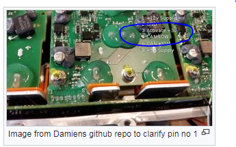
- image.png (119.97 KiB) Viewed 10701 times
which suggest that pin 3 is the activate and it needs 3V signal, but the table under suggest pin 3 to be low and pin 4 to have 3V.
I have connected my charger and when pin 3 is low (0V) and pin 4 is connected to 3V, there is no activity (both LEDs off and no CAN activity).
When I connect pin 3 to 3V, modules do come to life with one LED on (per module) and 15 different CAN messages per module. this looks like the correct wiring ar lest for my unit.
what should be the level for pin 4 ?
Thank you
Martin
Re: Tesla Charger Support thread gen2/gen3
Posted: Sun Dec 08, 2024 10:26 pm
by Matoleno
The contol board from Tesla Gen3 charger
Not sure is anyone is interrested, but I have "extracted" the control module and took some pistures. As I did not want to remove the phase modules and completely strip the charger (as I believe its working), I took sligtly different approach.
The board did sustain bit of damage when I was isolating it from the phase modules and then during removal, but not too much

If anyone is interrested in any details, please let me know.
and here are the pictures.

Re: Tesla Charger Support thread gen2/gen3
Posted: Wed Feb 12, 2025 2:04 pm
by medo
the page on the wiki really needs to be revised, some things are simply misleading
Re: Tesla Charger Support thread gen2/gen3
Posted: Wed Feb 12, 2025 3:42 pm
by tom91
medo wrote: ↑Wed Feb 12, 2025 2:04 pm
the page on the wiki really needs to be revised, some things are simply misleading
Please be specific, all you do is complain. Atleast provide concrete feedback.
Keep in mind the hardware and software variants that are out there, these have difference.
Re: Tesla Charger Support thread gen2/gen3
Posted: Sat Feb 15, 2025 12:35 pm
by medo
for me the pin designations are a bit misleading
would that be connected correctly???
Re: Tesla Charger Support thread gen2/gen3
Posted: Sat Feb 15, 2025 1:26 pm
by tom91
That drawing matches the pin numbering as its detailed.
Re: Tesla Charger Support thread gen2/gen3
Posted: Sat Feb 15, 2025 1:56 pm
by medo
I just don't know why no CAN messages come from the modules, all LEDs light up when they are activated