Erratic Speed Measurements  [SOLVED]

User avatar
GrapeNuts
Posts: 31
Joined: Sat Jan 05, 2019 2:27 am

Erratic Speed Measurements

Post by GrapeNuts »

Hello,

I've been wrestling with erratic speed plotting with my inverter. I'm at a loss how to troubleshoot this issue. I have an encoder which is providing 64 ppr. In this case, I've run the inverter in manual mode by starting it with the button on the web interface.

I'm running the inverter with the following values. According to the documentation this should provide a speed of 10hz. What RPM should I expect when running the inverter manually with these parameters? My optical tachometer reads the motor shaft is turning approximately 2300 RPM and the speed plot in the web interface is all over the place.

Code: Select all

fslipspnt 10
ampnom 70
Scope of encoder signal at ENC_IN_A:
Image

Shaft RPM measured by optical tach:
Image

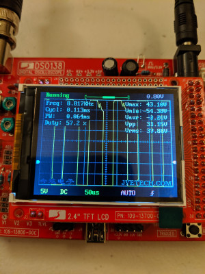
Erratic inverter speed plot:
Image

I have exported a copy of the parameters I used for this test run if they might be useful for diagnosis. I have the feeling I am making a simple mistake, but I just can't figure out problem. Any suggestions what I may need to correct?
nailgg
Posts: 119
Joined: Sat Dec 22, 2018 8:40 pm

Re: Erratic Speed Measurements

Post by nailgg »

Your scope reads 2315Hz, so for 64 PPR that's around 2170 RPM but I got confused with the info you provided. With 10 Hz, a 4-pole motor would spin at a synchronous speed of 300 RPM, so the rotor speed will be a little less than 300 because of the slip. What motor are you using?
User avatar
GrapeNuts
Posts: 31
Joined: Sat Jan 05, 2019 2:27 am

Re: Erratic Speed Measurements

Post by GrapeNuts »

Yeah I figured 2300 rpm is way too fast for 10Hz. I'm very confused why it spins so quickly.

Here is my motor nameplate:
Image
nailgg
Posts: 119
Joined: Sat Dec 22, 2018 8:40 pm

Re: Erratic Speed Measurements

Post by nailgg »

That's a 4-pole motor. What's your "polepairs" parameter value? It must be 2.
User avatar
GrapeNuts
Posts: 31
Joined: Sat Jan 05, 2019 2:27 am

Re: Erratic Speed Measurements

Post by GrapeNuts »

Yes I'm using 2, here is the export of the parameter values I'm using when I ran this test:

Code: Select all

{
  "boost": 1700,
  "fweak": 64.71,
  "fconst": 180,
  "udcnom": 0,
  "fslipmin": 1,
  "fslipmax": 3,
  "fslipconstmax": 5,
  "polepairs": 2,
  "respolepairs": 1,
  "encmode": 0,
  "fmin": 1,
  "fmax": 200,
  "numimp": 64,
  "dirchrpm": 100,
  "dirmode": 1,
  "syncofs": 0,
  "snsm": 12,
  "pwmfrq": 1,
  "pwmpol": 0,
  "deadtime": 63,
  "ocurlim": 100,
  "minpulse": 1000,
  "il1gain": 4.68,
  "il2gain": 4.68,
  "udcgain": 2.12,
  "udcofs": 136,
  "udclim": 540,
  "snshs": 0,
  "bmslimhigh": 50,
  "bmslimlow": -1,
  "udcmin": 450,
  "udcmax": 520,
  "iacmax": 5000,
  "idcmax": 5000,
  "idcmin": -5000,
  "throtmax": 100,
  "ifltrise": 10,
  "ifltfall": 3,
  "chargemode": 0,
  "chargecur": 0,
  "chargekp": 80,
  "chargeflt": 8,
  "chargemax": 90,
  "potmin": 0,
  "potmax": 4095,
  "pot2min": 4095,
  "pot2max": 4095,
  "potmode": 0,
  "throtramp": 100,
  "throtramprpm": 20000,
  "ampmin": 10,
  "slipstart": 50,
  "brknompedal": -50,
  "brkpedalramp": 100,
  "brknom": 30,
  "brkmax": -30,
  "brkrampstr": 10,
  "brkout": -50,
  "idlespeed": -100,
  "idlethrotlim": 50,
  "idlemode": 0,
  "speedkp": 0.25,
  "speedflt": 5,
  "cruisemode": 0,
  "udcsw": 330,
  "udcswbuck": 540,
  "tripmode": 0,
  "pwmfunc": 0,
  "pwmgain": 100,
  "pwmofs": 0,
  "canspeed": 0,
  "canperiod": 0,
  "fslipspnt": 10,
  "ampnom": 70
}
nailgg
Posts: 119
Joined: Sat Dec 22, 2018 8:40 pm

Re: Erratic Speed Measurements

Post by nailgg »

Have you tested it with the encoder disconnected? It should spin at 300 RPM at 10 Hz when there’s no encoder, i.e. speed feedback is zero.

How is the “encmode” set? I don’t know why but it’s not listed in the json parameter list you posted. It must be 0 if you’re using a single channel encoder. Also, if you were using double channel encoder before and just switched to a single channel one, there are some changes you must make on the encoder circuitry in your main board. We can focus on this if this is the case.

Edit: Ah I just saw encmode, it’s 0. So I guess something’s wrong with the populated components on your PCB. You can check out Johannes’ main site for the schematics.
User avatar
GrapeNuts
Posts: 31
Joined: Sat Jan 05, 2019 2:27 am

Re: Erratic Speed Measurements

Post by GrapeNuts »

Indeed, with the encoder disconnected the motor does spin at 300rpm.

My encoder actually supplies an A, B and Z channel but for troubleshooting I was running with encmode = single and only using the A channel of the encoder output. I would like to use A and B channels of the encoder output if possible. I was told not to use ABZ mode with an induction motor.

I haven't made any hardware modifications to the inverter board. Right now it has all components populated.
User avatar
GrapeNuts
Posts: 31
Joined: Sat Jan 05, 2019 2:27 am

Re: Erratic Speed Measurements

Post by GrapeNuts »

Also, I'm not sure if this is related but when I do switch to AB mode and attach both the A and B channels from the encoder when I start the inverter in manual mode the motor spins up clear to 6000 rpm. It's actually kind of scary considering the max rated RPM for this motor is 3600.
nailgg
Posts: 119
Joined: Sat Dec 22, 2018 8:40 pm

Re: Erratic Speed Measurements

Post by nailgg »

According to the documentation this should provide a speed of 10hz.
So when you set the fslipspnt to 10 Hz and have the encoder connected, it doesn’t mean that the inverter outputs constant 10 Hz, it just adds +10 Hz to the frequency it reads. So there’s no problem here :)

Is it a rev 2 main board? Did you buy it already populated, did you solder the components? If it’s a rev 2 board and to use it with AB encoder, just make sure if R1, R2, R4, R6, C1 and C3 are populated, J1 is unpopulated.

You cannot just switch from single channel to dual channel without altering the PCB, be careful with that :)
User avatar
GrapeNuts
Posts: 31
Joined: Sat Jan 05, 2019 2:27 am

Re: Erratic Speed Measurements

Post by GrapeNuts »

It's a rev 2. I populated the board from a kit. I did populate all components. I'll have to disassemble it and modify the components. So I must remove component J1?
nailgg
Posts: 119
Joined: Sat Dec 22, 2018 8:40 pm

Re: Erratic Speed Measurements

Post by nailgg »

GrapeNuts wrote: Sun May 12, 2019 11:42 pm Also, I'm not sure if this is related but when I do switch to AB mode and attach both the A and B channels from the encoder when I start the inverter in manual mode the motor spins up clear to 6000 rpm. It's actually kind of scary considering the max rated RPM for this motor is 3600.
You can set fmax to 100 to limit the inverter to 3000 RPM.
arber333
Posts: 3563
Joined: Mon Dec 24, 2018 1:37 pm
Location: Slovenia
Has thanked: 134 times
Been thanked: 335 times
Contact:

Re: Erratic Speed Measurements

Post by arber333 »

GrapeNuts wrote: Sun May 12, 2019 11:42 pm Also, I'm not sure if this is related but when I do switch to AB mode and attach both the A and B channels from the encoder when I start the inverter in manual mode the motor spins up clear to 6000 rpm. It's actually kind of scary considering the max rated RPM for this motor is 3600.
What kind of encoder are you using? How many PPR?
If you use some integer of 64PPR your inverter may have a feeling motor is not turning fast enough :).
Check the PPR rating or try to count pulses with certain RPM (cordless drill) and count dt on a scope.
I would set Fmax to the same value as Fweak.

EDIT: Did you check throttle calibration? Is it possible your throttle is so on the border it supplies signal even in manual mode? My throttle signal shifts if controler is turned on for like 50points. Must be some potential inside signal wires...
User avatar
johu
Site Admin
Posts: 6713
Joined: Thu Nov 08, 2018 10:52 pm
Location: Kassel/Germany
Has thanked: 369 times
Been thanked: 1543 times
Contact:

Re: Erratic Speed Measurements

Post by johu »

In fact you can leave J1 populated, it won't disturb operation in dual channel mode. Make sure to remove C3 though.
Support R/D and forum on Patreon: https://patreon.com/openinverter - Subscribe on odysee: https://odysee.com/@openinverter:9
User avatar
GrapeNuts
Posts: 31
Joined: Sat Jan 05, 2019 2:27 am

Re: Erratic Speed Measurements

Post by GrapeNuts »

Ok so after disassembly of my inverter it appears I have all components except J1 populated. With this hardware configuration I should be able to use both the A and B channels from my encoder correct?

Image

If I start the encoder manually via the web interface I should expect that it will run at 300 rpms?
User avatar
GrapeNuts
Posts: 31
Joined: Sat Jan 05, 2019 2:27 am

Re: Erratic Speed Measurements

Post by GrapeNuts »

Ok I think I'm making some progress but I think I have a fault somewhere. When I run manually with both A and B channels the motor takes off and spins up to around 2,600rpm for a shot period. Then it suddenly slows to around 150 rpm and starts to vibrate a bit while turning slowly.

Image

If I stop and restart the inverter I cannot get it to run past 150 rpms. I have to completely remove 12v power from the inverter and power it back on again. After doing that I'm able to run the motor again for a shot period before the cycle repeats.

Do I possibly have a fault in my power stage or maybe one of the gate drivers?
nailgg
Posts: 119
Joined: Sat Dec 22, 2018 8:40 pm

Re: Erratic Speed Measurements

Post by nailgg »

I doubt that would happen because of the faulty power stage. Have you checked that you still have a nice encoder feedback after the motor stalls? 150 rpm is 5 Hz, that's a close value to your fslipspnt value. Probably the encoder circuitry is still faulty.
User avatar
johu
Site Admin
Posts: 6713
Joined: Thu Nov 08, 2018 10:52 pm
Location: Kassel/Germany
Has thanked: 369 times
Been thanked: 1543 times
Contact:

Re: Erratic Speed Measurements

Post by johu »

Are you using gate drivers with some fault logic?
If the encoder were faulty the speed would be displayed as 0 and there wouldn't be any jitter. Also there is a considerable voltage drop on your udc. So can you verify the PWM on all channels after all? And also provide a plot including il1rms.
Support R/D and forum on Patreon: https://patreon.com/openinverter - Subscribe on odysee: https://odysee.com/@openinverter:9
User avatar
GrapeNuts
Posts: 31
Joined: Sat Jan 05, 2019 2:27 am

Re: Erratic Speed Measurements

Post by GrapeNuts »

I'm using the gate drivers provided with the kit.

Here is a plot with il1rms. (The il1rms value is hard to read, it is 1A.) This plot captures 3 faults. The inverter seemed to recover from the first fault but shortly after it fails twice more. There is a bus voltage drop at each fault and what looks like a momentary increase in current at index 1775.

The voltage drops are curious, perhaps an IGBT fault? The IGBT module is used industrial surplus from ebay. There is no guarantee it is working properly.

To check the PWM from the gate driver circuit I'll need to do some disassembly. I'll work on that now.

Image
User avatar
johu
Site Admin
Posts: 6713
Joined: Thu Nov 08, 2018 10:52 pm
Location: Kassel/Germany
Has thanked: 369 times
Been thanked: 1543 times
Contact:

Re: Erratic Speed Measurements

Post by johu »

What is your voltage source? It sags quite heavily. Yes I think you will need to scope a bit.
Can you put il1rms on the right axis, right now it's barely visible.
Support R/D and forum on Patreon: https://patreon.com/openinverter - Subscribe on odysee: https://odysee.com/@openinverter:9
nailgg
Posts: 119
Joined: Sat Dec 22, 2018 8:40 pm

Re: Erratic Speed Measurements

Post by nailgg »

GrapeNuts wrote: Wed May 15, 2019 2:13 am I'm using the gate drivers provided with the kit.

The voltage drops are curious, perhaps an IGBT fault? The IGBT module is used industrial surplus from ebay. There is no guarantee it is working properly.

Image
Unless the IGBTs you are using have some fault logic circuitry like IPM modules, I haven't seen an IGBT fail then recover from the fail after a power cycle. What IGBTs are you using?

Also if you are using the stock gate drivers you received from Johannes, I don't think that's a power stage fault because those gate drivers also don't have a logic that recovers from a fail after a power cycle, as far as I know.
User avatar
GrapeNuts
Posts: 31
Joined: Sat Jan 05, 2019 2:27 am

Re: Erratic Speed Measurements

Post by GrapeNuts »

For testing my DC voltage source is rectified mains with an isolation transformer.

Here are some images with il1rms plotted on the right.

Today there was a rough start with lots of vibration:
Image

Then for some period the motor was running fast and smooth:
Image

Then back to slow with vibration:
Image

I wanted to get those plots before I disassembled the inverter. What is the best way to scope the driver circuits? Do I need to disconnect their outputs from the IGBTs or can I scope while the outputs are still connected? (Of course I will have 0v on the DC bus if left connected.)

EDIT: I have scoped the driver circuits when fslipspnt = 1 and ampnom = 1. Here are the results.

All input signals look similar to this:
Image

All output signals look similar to this:
Image
nailgg
Posts: 119
Joined: Sat Dec 22, 2018 8:40 pm

Re: Erratic Speed Measurements

Post by nailgg »

Input and output signals look OK, but as your inverter fails intermittently you might have scoped the input/output signals when there was no fail. I would scope the gate driver output signals under normal operation when the motor slows down to 150 RPM. But you must be careful with this, it's a dangerous task. Not sure if you have the opportunity but I'd use a lab PSU with current limiting function as the DC voltage source to do this kind of testing. I'd also keep the DC voltage at low levels around 15-20 volts just to be safe. Normally you can leave the gate drivers connected to the IGBTs while scoping the G-E leads but never scope both low side and high side IGBTs at the same time unless you are using differential probes.
User avatar
GrapeNuts
Posts: 31
Joined: Sat Jan 05, 2019 2:27 am

Re: Erratic Speed Measurements

Post by GrapeNuts »

Ok, I think I found the problem. My second phase top output signal is different from the others with high voltage. The signals all look the same when I have 0v or low voltage on the DC bus, but when I have high voltage on the DC bus I see this only on one signal.

Image

Is this a damaged IGBT?
User avatar
johu
Site Admin
Posts: 6713
Joined: Thu Nov 08, 2018 10:52 pm
Location: Kassel/Germany
Has thanked: 369 times
Been thanked: 1543 times
Contact:

Re: Erratic Speed Measurements

Post by johu »

oh thats messy, I think you found the culprit. Now you can swap the gate driver to see if the error comes from the driver or the IGBT.
Support R/D and forum on Patreon: https://patreon.com/openinverter - Subscribe on odysee: https://odysee.com/@openinverter:9
User avatar
GrapeNuts
Posts: 31
Joined: Sat Jan 05, 2019 2:27 am

Re: Erratic Speed Measurements

Post by GrapeNuts »

Unfortunately I've had quite a bit of bad luck the last few days. When I took the measurement from my previous post I wasn't expecting that level of voltage on the driver outputs. I was using a 1x probe which fried my oscilloscope.

I borrowed a scope and I decided to troubleshoot with a lower DC bus voltage (170v) to prevent damage to my borrowed scope. I thought this would be safe because my borrowed scope has a 10x probe rated for 300v. I began troubleshooting and I swapped the output between 2 of the driver circuits. The fault was still present so I started measuring the output signals again. Unfortunately before I could figure out if the fault was with the driver circuit or IGBT I had a new event occur which I had not seen before.

When I started the inverter I had a large voltage spike on the DC bus. Fortunately my borrowed scope was not attached to the faulty circuit so it survived this event, but my voltage source did not. My isolation transformer when up in smoke. I guess some of the voltage also made its way back into the mains because my Kurieg is also not working this morning :(

Image

What could have caused this voltage increase? The DC bus voltage doubled. I've not see this before. At this point I need to order a bunch of new equipment to continue troubleshooting. Fortunately it seems the inverter has survived all these events.
Post Reply