Uncategorized files
Jump to navigation
Jump to search
Showing below up to 500 results in range #1 to #500.
 0000627 blogimages-2.jpg 826 × 419; 53 KB
 0000628 blogimages-1.jpg 795 × 625; 101 KB
 0010-000-004 R00 LEAF COUPLER.jpg 3,300 × 2,550; 916 KB
 036638-0002.jpg 2,100 × 1,991; 116 KB
 064320-1301.jpg 640 × 640; 23 KB
 064320-1311.jpg 640 × 640; 31 KB
 064323-1029.jpg 640 × 640; 16 KB
 064323-1039.jpg 640 × 640; 23 KB
 064325-1010.jpg 640 × 640; 19 KB
 064325-1023.jpg 640 × 640; 30 KB
 0B35D4F9-BA64-46E7-A570-A0CE1D619D63.jpg 1,512 × 2,016; 1.25 MB
 12V connected.jpg 2,218 × 3,228; 919 KB
 13 pin connector.png 122 × 85; 6 KB
 16-cell BMS.jpg 2,696 × 1,662; 727 KB
 1k resistor bent for SMD.jpg 2,350 × 1,403; 1.45 MB
 1n9hto6.jpg 2,000 × 1,500; 239 KB
 2005 Prius C5 Connector Pin Numbers.jpg.png 1,259 × 981; 1.44 MB
 2005 Prius Inverter Internal Connections.png 1,600 × 1,200; 2.47 MB
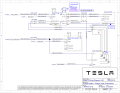 2012 ModelS LHD Release 16.1b.png 2,512 × 1,941; 502 KB
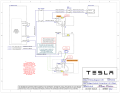 2012 ModelS LHD Release 24.2-3b.png 2,521 × 1,948; 451 KB
 2016-03-18 10-58-08 97-1024x576.jpg 1,024 × 576; 146 KB
 20200605 174452.jpg 4,032 × 2,268; 609 KB
 20200605 174924.jpg 2,268 × 4,032; 314 KB
 20200605 175047.jpg 2,268 × 4,032; 914 KB
 20200605 175849.jpg 2,268 × 4,032; 408 KB
 20200605 181654.jpg 2,268 × 4,032; 445 KB
 20200605 182754.jpg 2,268 × 4,032; 1.32 MB
 20200605 183933.jpg 1,332 × 1,220; 277 KB
 20200605 184633.jpg 2,268 × 4,032; 620 KB
 20200605 185543.jpg 1,660 × 1,056; 380 KB
 20200605 185557.jpg 2,268 × 4,032; 569 KB
 20200606 130213.jpg 2,268 × 4,032; 1.04 MB
 20200607 134336.jpg 2,968 × 2,268; 725 KB
 20200608 124947.jpg 2,268 × 4,032; 630 KB
 20200608 125053.jpg 2,268 × 4,032; 493 KB
 20200608 125110.jpg 1,724 × 2,864; 691 KB
 20200608 125857.jpg 2,268 × 4,032; 351 KB
 20200609 094633.jpg 1,872 × 3,568; 654 KB
 20200619 175629.jpg 2,838 × 1,596; 650 KB
 20200629 155303.jpg 4,032 × 2,268; 1.45 MB
 20200705 190657-2.jpg 4,032 × 2,268; 2.05 MB
 20200705 190657.jpg 4,032 × 2,268; 1.85 MB
 20200705 190706.jpg 4,032 × 2,268; 1.32 MB
 20200705 190723.jpg 4,032 × 2,268; 1.58 MB
 20200705 190723 2.jpg 4,032 × 2,268; 1.62 MB
 20200720 151129.jpg 4,032 × 2,268; 1.64 MB
 20200720 151132.jpg 4,032 × 2,268; 1.72 MB
 20200720 151136.jpg 4,032 × 2,268; 1.75 MB
 20200720 151141.jpg 4,032 × 2,268; 606 KB
 20200801 164706.jpg 2,268 × 4,032; 1.6 MB
 20200801 164710.jpg 2,268 × 4,032; 1.4 MB
 20200801 180635.jpg 2,268 × 4,032; 1.67 MB
 20200801 180830.jpg 2,268 × 4,032; 1.48 MB
 20200801 182148.jpg 2,268 × 4,032; 385 KB
 20200801 182238.jpg 2,268 × 4,032; 1.42 MB
 20200801 183613.jpg 2,268 × 4,032; 1.29 MB
 20200801 183950.jpg 4,032 × 2,268; 695 KB
 20200801 221733.jpg 2,268 × 4,032; 881 KB
 20200802 080902.jpg 2,268 × 4,032; 285 KB
 20200802 080907.jpg 2,268 × 4,032; 718 KB
 20201029 130555.jpg 3,024 × 4,032; 461 KB
 20201124 214308.jpg 2,635 × 1,482; 804 KB
 20210114 162937.jpg 2,268 × 4,032; 596 KB
 20210114 172258.jpg 2,268 × 4,032; 514 KB
 20210114 172503.jpg 2,268 × 4,032; 523 KB
 20210114 172710.jpg 2,268 × 4,032; 560 KB
 20210114 173552.jpg 2,268 × 4,032; 348 KB
 20210114 174343.jpg 2,268 × 4,032; 410 KB
 20210119 110057.jpg 2,268 × 4,032; 273 KB
 20210119 125158.jpg 2,268 × 4,032; 917 KB
 20210119 191934.jpg 1,932 × 2,208; 393 KB
 20210208 161123.jpg 2,268 × 4,032; 1.72 MB
 20210209 165419.jpg 898 × 1,596; 185 KB
 20210209 182058.jpg 2,268 × 4,032; 1.37 MB
 20210210 125754.jpg 2,268 × 4,032; 819 KB
 20210210 140247.jpg 2,268 × 4,032; 589 KB
 20210210 140301.jpg 2,268 × 4,032; 1.23 MB
 20210210 140438.jpg 2,268 × 4,032; 827 KB
 20210210 152916.jpg 2,268 × 4,032; 293 KB
 20210211 162238.jpg 4,032 × 2,268; 504 KB
 20210211 182621.jpg 2,275 × 1,006; 237 KB
 20210211 182629.jpg 834 × 1,482; 120 KB
 20210211 182635.jpg 834 × 1,482; 130 KB
 20210212 135323.jpg 2,268 × 4,032; 398 KB
 20210213 173552.jpg 4,032 × 2,268; 1.74 MB
 20210224 112245.jpg 2,268 × 3,036; 1.37 MB
 20210224 112252.jpg 2,268 × 3,159; 1.38 MB
 20210325 222043.jpg 2,268 × 4,032; 480 KB
 20210329 134301.jpg 898 × 1,596; 161 KB
 20210421 124814 (1).jpg 2,128 × 1,596; 994 KB
 20210425 143144 (1).jpg 4,032 × 2,268; 3.75 MB
 20210425 152953.jpg 4,032 × 2,268; 3.16 MB
 20211011 113810.jpg 2,268 × 4,032; 1.17 MB
 20211011 113847.jpg 2,268 × 4,032; 320 KB
 20220119 201352.jpg 4,032 × 1,816; 1.88 MB
 20220616 153133.jpg 4,032 × 3,024; 1.34 MB
 20220712 131123.jpg 1,886 × 1,414; 133 KB
 20220712 172319.jpg 1,146 × 1,528; 184 KB
 20220818 123558.jpg 3,024 × 4,032; 3.5 MB
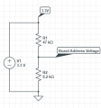 3.3v Addressing Voltage Divider.png 350 × 376; 12 KB
 300a 450v Fuse.jpg 3,682 × 1,749; 1.05 MB
 32 Pin Main Inverter connector .png 2,128 × 1,196; 6.2 MB
 32 position 90° headers.png 947 × 548; 134 KB
 3dprint locations1.jpg 1,226 × 920; 120 KB
 3dprint locations2.jpg 1,226 × 920; 105 KB
 3dprint locations3.jpg 1,226 × 920; 111 KB
 3phase light bulbs.jpg 3,000 × 4,000; 3.08 MB
 4-cell module.jpg 1,205 × 1,638; 223 KB
 40 pos. conn back.png 277 × 673; 48 KB
 40 pos. conn front V0.0.4.png 359 × 758; 71 KB
 40 pos conn back.png 390 × 879; 72 KB
 40 pos female housing pin labeling.png 1,668 × 796; 222 KB
 40 position 90° headers.png 938 × 555; 141 KB
 40 position connector front V0.0.4.png 441 × 857; 87 KB
 40kwh Nissan Leaf BMS.jpg 4,032 × 3,024; 1.18 MB
 40pos. pin out back.png 370 × 1,068; 99 KB
 40pos. pin out front.png 376 × 1,112; 116 KB
 40pos pin out.png 355 × 1,109; 110 KB
 40pos pin out back.png 381 × 1,085; 108 KB
 40pos pinout back.png 241 × 714; 55 KB
 51872869539 19178b9a51 o.jpg 1,826 × 2,079; 934 KB
 6-pin-outlander-phev-motor-connector.png 505 × 66; 1 KB
 6879B701-0DB1-44B4-9051-8A35259B27B9.jpg 800 × 685; 135 KB
 74712D46-548E-4598-B4E9-78A7C2EE93E1.jpg 1,440 × 1,439; 603 KB
 8-pin-outlander-phev-motor-connector.png 505 × 66; 1 KB
 8pin-Female-Sealed-Auto-Wire-6189-1240-Sumitomo-Connector.jpg 800 × 800; 33 KB
 9200-30131-inverter side.png 1,510 × 1,136; 96 KB
 9200-30131-named-inverter side.png 1,512 × 1,138; 88 KB
 9511A7C4-6DEB-47F1-A4AA-D0C0267F70E0.jpg 800 × 568; 102 KB
 966D2AF0-312F-4A8D-8980-0B13C9BDF92A.jpg 395 × 700; 120 KB
 9DDD088D-D9EA-44FC-B155-2E6C5C2D594F.jpg 2,448 × 3,264; 2.05 MB
 9 Leaf Controller Outside World Connector de-soldered.jpg 900 × 1,789; 345 KB
 A09A7625.jpg 1,280 × 853; 369 KB
 A09A7628.jpg 1,280 × 853; 401 KB
 A09A7632.jpg 1,280 × 853; 439 KB
 A09A7633.jpg 1,280 × 853; 293 KB
 A09A7634.jpg 1,280 × 853; 353 KB
 A09A7763.jpg 687 × 1,280; 301 KB
 AC Connection.jpg 1,060 × 1,414; 118 KB
 AC Connection2.jpg 1,060 × 1,414; 130 KB
 AC DC Connections.jpg 600 × 337; 43 KB
 AC Input VW PHEV Charger.jpg 2,013 × 1,843; 875 KB
 AMPSeal socket (male).jpg 1,200 × 900; 274 KB
- Error creating thumbnail: File with dimensions greater than 12.5 MPAMPSeal socket with pins marked.jpg 4,608 × 3,456; 2.82 MB
 ATSS SPL.webp 266 × 270; 4 KB
 ATSSi.jpg 300 × 300; 19 KB
 Adapter Board pin outs.png 4,579 × 2,509; 5 MB
 Adapter board pin outs.png 400 × 219; 117 KB
 Adapter plate.jpg 4,032 × 3,024; 744 KB
 Adapter plate CAD .jpg 2,448 × 3,264; 1.26 MB
 Ade910b746c28a30f6e6e2c9086c.jpg 2,560 × 1,920; 577 KB
 Alternating.jpg 2,268 × 4,032; 5.7 MB
 Ampera-dc-dc-converter.jpg 1,490 × 1,133; 240 KB
 Ampera DC-DC converter.jpg 3,264 × 2,448; 1.57 MB
 Ampera DCDC .jpg 768 × 1,024; 271 KB
 Ampera Volt gen1 charger.jpg 768 × 1,024; 342 KB
 Ampseal board.png 400 × 249; 26 KB
 Annotated Nissan Leaf Precharge Circuit.jpg 1,729 × 2,305; 1.01 MB
 Arduino CAN bus shield connected to Isabellenhütte IVT-S.jpg 800 × 1,067; 354 KB
 Arduino Uno CAN bus shield.jpg 800 × 600; 136 KB
 Assembled inverter.jpg 900 × 789; 122 KB
 Assembled inverter controller.jpg 900 × 684; 93 KB
 Assembled inverter gate driver.jpg 900 × 536; 64 KB
 Assembled inverter inside.jpg 900 × 721; 85 KB
 Audi A2 Conversion.png 1,236 × 700; 1,008 KB
 BMS Board.jpg 1,280 × 585; 313 KB
 BMS CTL BOARD.jpg 2,609 × 1,573; 1.04 MB
 BMS MASTER WIRES.jpg 2,219 × 2,312; 1.01 MB
 BMS MODULE.jpg 2,292 × 1,199; 520 KB
 BMS Master Unit.jpg 520 × 377; 35 KB
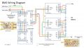
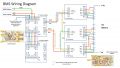 BMS Wiring Diagram.jpg 1,440 × 810; 228 KB
 BMW-i3-LIM-CCS-charging-voltage-sense-board-measuring.jpg 600 × 450; 79 KB
 BMW 5 Modules Pack.jpg 800 × 450; 139 KB
 BMW 6 Module pack.jpg 660 × 451; 155 KB
 BMW E46 Throttle Pedal.png 1,376 × 738; 33 KB
 BMW E46 Throttle Pedal ETK.png 1,017 × 719; 130 KB
 BMW E60 Throttle Pedal.png 1,174 × 521; 27 KB
 BMW E60 Throttle Pedal ETK.png 800 × 560; 157 KB
 BMW E87 Throttle Pedal.png 1,551 × 711; 37 KB
 BMW F-Series Gear Selector.png 799 × 561; 212 KB
 BMW I3 2016 Factory Workshop Service Repair Manual 2563-4b.png 4,370 × 2,043; 124 KB
 BMW I3 CCS Labelled.png 300 × 400; 194 KB
 BMW I3 inverter.jpg 800 × 531; 78 KB
 BMW S-box.jpg 1,599 × 1,201; 329 KB
 Battery Location.jpg 770 × 314; 37 KB
 Block diagram can id translation (draft).jpg 2,480 × 3,507; 1.11 MB
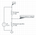 Board address voltage divider.png 599 × 580; 28 KB
 Boost Mode Connection.png 1,176 × 756; 14 KB
 Boost mode variant.png 1,293 × 831; 16 KB
 Boxster EV.png 780 × 502; 1.05 MB
 Broken isospi.gif 774 × 1,376; 394 KB
 Buck Mode Connection.png 1,463 × 762; 22 KB
 CAN bus messages on serial console.jpg 800 × 1,067; 278 KB
 CAN bus shield fitted to Arduino Uno.jpg 800 × 600; 172 KB
 CAN repeater.jpg 1,655 × 1,676; 423 KB
- Error creating thumbnail: File with dimensions greater than 12.5 MPCCS1 vs CCS2 signaling circuit.png 21,220 × 4,902; 1.01 MB
 CCS1 vs CCS2 signaling circuit 2.png 995 × 946; 320 KB
 CCS2-inlet.jpg 403 × 527; 134 KB
 CCS setup LIM-01.png 2,346 × 1,093; 207 KB
 CCS setup LIM 2-02.png 817 × 309; 34 KB
 CCS setup LIM 2-03.png 2,584 × 803; 59 KB
 CCur.png 816 × 414; 27 KB
 CHAdeMO-LeafVCU (1).png 1,600 × 900; 986 KB
 CVolt.png 815 × 413; 98 KB
 Can mapping chademo.png 1,390 × 910; 141 KB
 Ccs-socket.jpg 800 × 800; 67 KB
 ChaDeMo socket in Touran.jpg 3,264 × 2,448; 2.01 MB
 Chademo Wiring.png 1,492 × 592; 299 KB
 Chemvolt.png 738 × 202; 35 KB
 Clanger boost idea.png 720 × 405; 93 KB
 ClipsOnPins-LDUEncoder.jpg 600 × 677; 217 KB
 Commands.png 1,232 × 610; 56 KB
 Conboxuntouched.webp 1,920 × 1,440; 161 KB
 Connector-Tesla-AC-compressor.png 342 × 256; 22 KB
 Connector-Tesla-FJB.png 766 × 621; 112 KB
 Connector - A55 Oil Pump Motor Controller 90980–12483.png 269 × 201; 7 KB
 Connector PCB screws.jpg 1,986 × 3,745; 4.84 MB
 Connector Secured.jpg 1,651 × 2,148; 2.69 MB
 Contactor Control.jpg 3,579 × 2,426; 2.21 MB
 Coolant Inlet-Outlet.jpg 1,552 × 843; 267 KB
 Coupler box section profile.jpg 1,280 × 853; 169 KB
- Error creating thumbnail: File with dimensions greater than 12.5 MPCurrent Shunt.jpg 5,760 × 3,840; 9 MB
 Current sense board.jpg 1,000 × 465; 84 KB
 D-217-1.png 70 × 54; 3 KB
 DC-DC converter C5 Connector.png 1,259 × 981; 1.87 MB
 DCDCTESLA.jpg 892 × 297; 26 KB
 DCDC Connector wiring.jpg 654 × 566; 124 KB
 DSC03474-1000x700.jpg 1,000 × 700; 211 KB
 Dcdcpins.jpg 467 × 386; 55 KB
 Debug.png 1,249 × 792; 216 KB
 Denso-ES34C-HV-polarity.jpg 705 × 529; 71 KB
 Der Panzer.png 792 × 440; 444 KB
 DialogWin2.png 673 × 680; 87 KB
 Drive Inverter Front Connector.png 1,213 × 940; 116 KB
 Drive Inverter Front Connector Schematic.png 1,120 × 498; 89 KB
 Due CAN bus logger with SD card storage.jpg 4,032 × 3,024; 3.21 MB
 Due CAN loopback test.jpg 4,032 × 3,024; 3.76 MB
 Due SPI pins.png 768 × 480; 288 KB
 E-Golf Slave board.jpg 2,665 × 1,500; 1.75 MB
 E-Golf Slave board part 2.jpg 2,665 × 1,500; 1.92 MB
 E-Golf contactor block.jpg 2,743 × 1,543; 1.73 MB
 E-Golf pack cover off 1.jpg 2,693 × 1,148; 1.84 MB
 E-Golf pack cover off 2.jpg 2,895 × 1,244; 1.61 MB
 E-Golf pack cover off 3.jpg 1,814 × 1,681; 1.45 MB
 EED7575E-BDAF-44F3-A438-46865EE83F5B.jpg 300 × 400; 64 KB
 EM61.png 1,496 × 994; 1.99 MB
 ERNI Microbridge adapter board.png 400 × 249; 22 KB
 ERNI Minibridge.jpg 1,920 × 2,560; 1.84 MB
 ERNI Minibridge Connector.jpg 1,920 × 2,560; 2.1 MB
 ESP32-Chademo.jpg 2,878 × 3,102; 214 KB
 ESP32.png 1,106 × 536; 115 KB
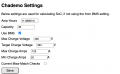 ESP32 Chademo settings.png 1,226 × 756; 99 KB
 ESP32 programming header.png 845 × 597; 62 KB
 ESP8266 communication with DuPont jump leads and without.png 1,312 × 912; 632 KB
 Early-Tesla-airconditioning-compressor.png 342 × 256; 147 KB
 Eaton Bussmann FWH-50B Semiconductor fuses.jpg 3,024 × 4,032; 1.92 MB
 Egolf charger.jpg 2,560 × 1,440; 1.43 MB
 Eltek Valere IP20.jpg 552 × 736; 157 KB
 Eltek Valere IP67.jpg 768 × 576; 215 KB
 Em57.jpg 1,600 × 1,067; 170 KB
 Em61 motor.png 1,278 × 668; 953 KB
 Empty.png 36 × 31; 160 bytes
 Errata Voltage Sense 1.jpg 1,200 × 900; 132 KB
 Errata Voltage Sense 2.jpg 1,200 × 900; 112 KB
 Esp8266-flash.png 798 × 173; 7 KB
 Esp8266 debugging help.png 1,398 × 928; 675 KB
 Example Ebay Listing.png 1,462 × 653; 504 KB
 Ext connector view 1.jpg 2,579 × 1,927; 948 KB
 Ext connector view 2.jpg 2,177 × 1,783; 752 KB
 Fiesta clutch on Mitsubishi outlander front motor..jpg 1,536 × 2,047; 222 KB
 FirstRun.png 1,918 × 1,078; 669 KB
 Flange-spacings.jpg 3,024 × 4,032; 3.22 MB
 Foccci pinout.svg 1,052 × 744; 1.5 MB
 Formular udc.png 258 × 42; 3 KB
 Front adapter board SMD components.png 1,163 × 924; 218 KB
 Front view, note different numbering.jpg 4,032 × 2,268; 6 MB
 Fuses Bussmann-Eaton FWH-50B 02b.jpg 1,000 × 488; 42 KB
 Fweak.png 210 × 55; 5 KB
 GS300hShiftsensor.png 400 × 381; 188 KB
 GS450H-3D-PRINTABLE-HV-INLET.jpg 2,080 × 1,560; 270 KB
- Error creating thumbnail: File with dimensions greater than 12.5 MPGS450H HV Inlet.jpg 4,160 × 3,120; 335 KB
- Error creating thumbnail: File with dimensions greater than 12.5 MPGS450H HV Inlet .jpg 4,160 × 3,120; 458 KB
- Error creating thumbnail: File with dimensions greater than 12.5 MPGS450H HV Inlet sml.jpg 4,160 × 3,120; 291 KB
 GS450H Inlet Blank .jpg 2,775 × 3,271; 378 KB
 GS450h L110 Transmission.jpg 640 × 480; 51 KB
 GS450h oil pump check.jpg 745 × 835; 209 KB
 GS450h oil pump controller.jpg 888 × 652; 115 KB
 GT86.png 1,176 × 636; 1.22 MB
 Gate driver.jpg 900 × 888; 99 KB
 Gearbox oil pump PWM.jpg 737 × 564; 92 KB
 Gen2.jpg 1,600 × 1,200; 150 KB
 Gen2 Charger V5aB2 logic board.jpg 3,264 × 2,448; 2.45 MB
 Gen2 Prius DC-DC Connections.jpg 1,221 × 856; 170 KB
 Gen2 internals.jpg 1,391 × 926; 380 KB
 Gen3Pin out.png 400 × 145; 42 KB
 Gen 2 gears.jpg 960 × 1,280; 295 KB
 Gen 3 PC board assembly.png 1,588 × 1,127; 283 KB
 Gigavac contactor driver circuit.png 966 × 316; 22 KB
 Git commandline 2.jpg 1,029 × 447; 79 KB
 Gm-dcdc-hvconn.png 344 × 400; 80 KB
 Gs300h-cvt-lhs-annotated-2.jpg 1,339 × 848; 181 KB
 Gs300h-cvt-lhs-annotated.jpg 1,339 × 848; 181 KB
 Gs300h-cvt-rhs-annotated-2.jpg 1,239 × 1,000; 191 KB
 Gs300h-cvt-rhs-annotated.jpg 1,239 × 1,000; 191 KB
 Gs300h-cvt.jpg 1,600 × 1,066; 220 KB
 Gs450h-inverter-wires.jpg 1,560 × 2,080; 468 KB
- Error creating thumbnail: File with dimensions greater than 12.5 MPGs450h HV inlet.jpg 4,160 × 3,120; 2.82 MB
 Gs450h gearbox oil pump pwm.jpg 944 × 468; 108 KB
- Error creating thumbnail: File with dimensions greater than 12.5 MPGs450h inverter inlet blank.jpg 3,120 × 4,160; 2.52 MB
 HV wiring.jpg 2,555 × 1,806; 410 KB
 Hc con 2.jpg 2,392 × 2,048; 995 KB
 Heater Connector Pins.png 228 × 116; 13 KB
 Height.jpg 1,886 × 1,414; 204 KB
 High Voltage Cables.jpg 800 × 560; 83 KB
 High speed plot.png 1,570 × 628; 116 KB
 Hla009286001.webp 946 × 864; 36 KB
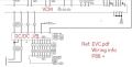
 Huebner BMS Wiring Diagram.jpg 1,440 × 810; 233 KB
 Hv con 1.jpg 2,412 × 2,029; 1,006 KB
 Hv con 3.jpg 2,215 × 1,751; 851 KB
 HybridFrameSizes.png 442 × 288; 11 KB
 I3 ccs port wiring.jpg 1,600 × 689; 139 KB
 IEC61851 charging sequence.png 1,800 × 1,135; 314 KB
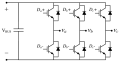 IGBT-Bridge-Configuration.png 850 × 438; 20 KB
 IPDM56 USB power up.jpg 1,024 × 1,236; 1.51 MB
 IPM wiring.jpg 549 × 313; 22 KB
 ISA shunt in Touran pack.jpg 4,000 × 1,800; 1.23 MB
 IVT-S 1000A CAN Shunt.jpg 640 × 480; 120 KB
 IVT-S Current Shunt.jpg 161 × 144; 13 KB
 IVT-S Mating Plug.png 635 × 243; 44 KB
 IVT-S front and behind image .jpg 640 × 480; 126 KB
 Igbt module schematic.jpg 200 × 155; 11 KB
 Image.png 717 × 443; 812 KB
 Img 0014.jpg 400 × 300; 45 KB
 Img 20210328 195231.jpeg 768 × 1,024; 258 KB
 Img 20210328 195231.jpg 768 × 1,024; 258 KB
 Img 20210616 210202.jpg 1,024 × 768; 259 KB
 Initial.png 1,713 × 889; 536 KB
 Inside gen2 gearbox.jpg 1,600 × 1,067; 225 KB
 Int connector view 1.jpg 1,290 × 1,142; 217 KB
 Int connector view 2.jpg 1,723 × 1,698; 455 KB
 Inverter.png 2,434 × 849; 234 KB
 Inverter UVW.png 589 × 337; 33 KB
 Inverter connections.png 1,238 × 562; 49 KB
 Inverter connector.png 690 × 855; 23 KB
 Inverter entry board harness.jpg 1,913 × 1,559; 494 KB
 Isa connections CAN and U sense.png 1,500 × 1,500; 467 KB
 Isolator module.jpg 1,774 × 899; 222 KB
 J497.jpg 1,952 × 2,602; 1.85 MB
 J840.jpg 1,906 × 2,541; 1.76 MB
 Jumpers soldered.jpg 4,032 × 2,268; 6.34 MB
 Kangoo Contactor box.jpg 4,000 × 3,000; 2.86 MB
 Kangoo Disconnect.jpg 3,000 × 4,000; 2.56 MB
 Kangoo Midpack Fuse.jpg 3,000 × 4,000; 3.08 MB
 L210-flange-guibo.jpg 3,012 × 2,974; 2.65 MB
 L210 Schematic.png 700 × 264; 59 KB
 LDU connection diagram.png 1,712 × 1,199; 483 KB
 LEXUS RX 400H 2004-2008 209048010.jpg 800 × 534; 100 KB
 LR gear selector - gen 1.jpg 2,145 × 3,705; 1.62 MB
 LR gear selector - gen 2.jpg 1,729 × 2,209; 800 KB
 LS600hL L110F Transmission.jpg 598 × 406; 35 KB
 LeafGearbox.jpg 1,600 × 1,200; 477 KB
 Leaf Gen.3.png 1,321 × 935; 763 KB
 Leaf adapter pin map.png 281 × 896; 37 KB
 Leaf coupler.jpg 4,032 × 3,024; 733 KB
 Leaf inverter pinout.jpg 791 × 927; 123 KB
 Leaf resolver pinout.png 602 × 931; 61 KB
 Leafgearbox.jpg 1,600 × 1,067; 235 KB
 Leafpump.png 1,800 × 789; 452 KB
 Legs attached for pull test.jpg 2,383 × 2,268; 3.33 MB
 Length.jpg 1,886 × 1,414; 165 KB
 Logic Encoder1.png 1,449 × 258; 27 KB
 M3 HVS Pinout.jpg 1,330 × 1,774; 512 KB
 M3conetor.png 400 × 246; 158 KB
 MCur.png 815 × 410; 93 KB
 MG1 Resolver and Temperature Sensor.jpg 2,759 × 3,024; 1.98 MB
 MG2 Resolver Gen 3.jpg 2,993 × 2,935; 1.72 MB
 MG2 Temperature Sensor.jpg 2,974 × 3,465; 2.9 MB
 MVolt.png 816 × 407; 40 KB
 Main board v1.jpg 1,280 × 1,000; 208 KB
 Main board v2.jpg 1,200 × 911; 254 KB
 Main board v3.jpg 597 × 611; 101 KB
 Main board v3 .jpg 3,509 × 2,480; 688 KB
 MainboardV3Test.jpeg 1,140 × 1,048; 291 KB
 Mainboard connections v1.jpg 540 × 556; 69 KB
 Mainboard connections v2.jpg 1,000 × 1,029; 238 KB
 Mainboard pinout v3.png 887 × 678; 29 KB
 Maintenance tool step 1.jpg 950 × 631; 54 KB
 Maintenance tool step 2.jpg 952 × 632; 143 KB
 Mercedes Brusa LV Pinout A.jpg 825 × 734; 105 KB
 Mercedes Brusa LV Pinout B.jpg 824 × 724; 104 KB
 Mini mainboard.png 570 × 675; 134 KB
 Mini mainboard Transparent.png 570 × 675; 201 KB
 Mini mainboard front.jpg 1,124 × 1,776; 368 KB
 Mitsubishi Outlander PHEV dimensions.jpg 1,512 × 2,016; 853 KB
 Mitsubishi Outlander PHEV height.jpg 1,512 × 2,016; 609 KB
 Mitsubishi Outlander Rear Motor Inverter (REMCU) Control Wiring (2019 Model).png 1,032 × 760; 182 KB
 MleebertTestDiagram.svg 121 × 61; 1 KB
 MleebertTestDiagramsvg.svg 121 × 61; 1 KB
 MleebertTestDiagramsvgsvg.svg 121 × 61; 1 KB
 Model 3 US charger variant AC connector.png 627 × 452; 550 KB
 Mods to enable CAN bus done.jpg 2,086 × 2,331; 4.02 MB
 Molex 194180026 .png 1,719 × 1,126; 169 KB
 Molex 19420-0010.png 978 × 691; 204 KB
 Molex 42815-0134.png 1,042 × 459; 190 KB
 Molex 42816-0312.png 504 × 306; 56 KB
 Molex 42816-0412 .png 549 × 327; 71 KB
 Molex 8 AWG open barrel terminal.jpg 1,904 × 1,283; 286 KB
 Motor Transmission Coupler.jpg 1,280 × 853; 195 KB
 Motor bracket.jpg 3,264 × 2,448; 2.32 MB
 Motor connector.jpg 1,000 × 667; 115 KB
 New-Doc-2018-12-26-20.25.04 1.jpg 768 × 616; 41 KB
 NissanLeafV2BMS.jpg 3,264 × 2,448; 2.05 MB
 Nissan Leaf BMS Connector Pins LB11 LB12.png 1,632 × 1,114; 1.26 MB
 Nissan Proprietary connector.jpg 2,976 × 3,968; 5 MB
 Nissan inverter board.jpg 3,968 × 2,976; 4.29 MB
 Numbering scheme.jpg 4,032 × 2,268; 5.88 MB
 Oil Pump.png 607 × 577; 30 KB
 Oil Pump2.png 837 × 491; 33 KB
 Oilpump.png 625 × 601; 38 KB
 OpPoint.png 338 × 331; 17 KB
 Opel Astra Power Steering Pump.jpg 2,560 × 1,920; 577 KB
 Opel Astra Power Steering Pump Harness.jpg 1,600 × 900; 128 KB
 Opel Astra Power Steering Pump Harness (Bosch).jpg 1,600 × 900; 149 KB
 Openinverter i3 drop-in board.jpg 3,264 × 2,448; 2.24 MB
 Original Pipework Conector.jpg 853 × 1,280; 234 KB
 Outlander AC Compressor.jpg 2,048 × 1,536; 325 KB
 Outlander BMU CAN Connections.png 658 × 328; 63 KB
 Outlander DC-DC OBC Signal Connector.jpg 1,425 × 1,466; 413 KB
 Outlander DCDC OBC 12V Cap.jpg 2,496 × 1,898; 804 KB
 Outlander Front Clutch.jpg 3,024 × 4,032; 640 KB
 Outlander Heater HV.jpg 862 × 1,532; 190 KB
 Outlander REMCU.png 1,546 × 844; 80 KB
 Outlander REMCU Wiring.png 1,023 × 695; 182 KB
 Outlander Rear Motor.jpg 1,636 × 920; 284 KB
 Outlander Rear Motor Face.jpg 1,920 × 1,080; 137 KB
 Outlander Rear Motor Length.jpg 780 × 1,040; 99 KB
 Outlander harness.jpg 4,054 × 1,763; 1,020 KB
 Outlander internals bottom.jpg 2,735 × 4,096; 6.84 MB
 Outlander internals top.jpg 2,735 × 4,096; 7.33 MB
 Outlander phev charger dimensions.jpg 1,512 × 2,016; 756 KB
 PCS Alert Table001.jpg 4,032 × 2,268; 5.91 MB
 PCS Alert Table002.jpg 4,032 × 2,268; 5.33 MB
 PC board assembly.png 1,585 × 1,122; 279 KB
 PDM PINOUT.png 544 × 807; 75 KB
 PXL 20210514 092652934-min.jpg 4,032 × 3,024; 902 KB
 PXL 20220212 221048871.jpg 2,725 × 1,490; 752 KB
 PXL 20220624 072540901.jpg 2,680 × 1,508; 934 KB
 PXL 20220624 072610756.jpg 2,680 × 1,508; 957 KB
 PXL 20220624 072941220.jpg 2,680 × 1,508; 630 KB
 PXL 20231125 230415175~2.jpg 1,089 × 1,154; 161 KB
 P t.png 436 × 408; 28 KB
 Panasonic AEV14012.jpg 3,000 × 4,000; 2.92 MB
 Parameter view of commercial firmware.png 799 × 1,052; 101 KB
 Parameters.png 779 × 943; 93 KB
 Passat HV Contactor.jpg 2,659 × 3,157; 1.24 MB
 Pc board SMD only.png 1,411 × 1,111; 280 KB
 Perforate the seal with multimeter probe.jpg 4,032 × 2,268; 6.65 MB
 Peugeot TPS pinout.jpg 400 × 320; 40 KB
 Pinout.png 1,280 × 720; 79 KB
 Pinout V1.jpg 3,264 × 1,836; 1.03 MB
 Pins and jumpers.jpg 2,561 × 1,569; 2.48 MB
 Placard.jpg 698 × 524; 64 KB
 Plastic grid removed, note different numbering.jpg 4,032 × 2,268; 5.82 MB
 Plot.png 936 × 557; 65 KB
 Polo front.jpg 1,200 × 900; 244 KB
 Polo front batteries.jpg 1,200 × 900; 214 KB
 Polo motor inverter.jpg 1,200 × 900; 176 KB
 Polo rear batteries.jpg 1,200 × 900; 168 KB
 Possible ccs take off.png 400 × 267; 234 KB
 Power supply.png 400 × 98; 20 KB
 Pre Charge Relay.jpg 1,259 × 969; 214 KB
 Pre charge relay.jpg 969 × 1,259; 239 KB
 Precharge.png 325 × 289; 4 KB
 Prechargerelay.jpg 1,576 × 2,100; 873 KB
 Prius3-ldo2.jpg 1,200 × 1,600; 242 KB
 Prius Board v1.jpg 1,024 × 910; 176 KB
 Prius Control Board - Wiring Map.png 1,846 × 986; 2.73 MB
 Prius Control Board Wiring Diagram.jpg 2,298 × 1,336; 712 KB
 Prius Control Board Wiring Map.jpg 2,298 × 1,336; 746 KB
 Prius GEN 2 C5 Connector Pinout.png 1,259 × 981; 1.7 MB
 Prius GEN 2 C 5 Connector Pinout.png 1,259 × 981; 1.7 MB
 Prius GEN 2 logic board wiring diagram.jpg 2,298 × 1,336; 716 KB
 Prius Gen2 Inverter - Internal.jpg 1,024 × 744; 138 KB
 Prius Gen2 inverter internals.jpg 1,391 × 926; 381 KB
 Prius Gen2 inverter schematic.gif 768 × 576; 29 KB
 Prius Gen2 logic board wiring diagram.jpg 2,298 × 1,336; 720 KB
 Prius Gen3 - Auris - Yaris Connector Body .jpg 400 × 225; 37 KB
 Prius Gen3 Inverter Control v2.jpg 3,264 × 1,836; 992 KB
 Prius Gen 2 "C 5" Connector.png 1,259 × 981; 1.75 MB
 Prius Gen 2 Inverter.jpg 1,024 × 893; 135 KB
 Prius Gen 2 Layout.jpg 800 × 594; 139 KB
 Prius Gen 2 inverter lower casing internals.png 1,920 × 1,080; 3.38 MB
 Prius Gen 2 inverter montage.jpg 1,920 × 1,077; 794 KB
 Prius Gen 2 logic board(BluePill-based).jpg 2,032 × 1,248; 615 KB
 Prius Gen 2 logic board wiring diagram..jpg 2,298 × 1,336; 705 KB
 Prius Inverter - Pin Numbering.png 969 × 458; 801 KB
 Prius Inverter - Pin Numbering 2.jpg 968 × 919; 141 KB
 Prius Inverter Wire Colors 2.jpg 1,024 × 410; 55 KB
 Prius Inverter Wire Colors 3.jpg 1,024 × 536; 75 KB
 Prius Inverter Wire Colors 4.jpg 1,024 × 605; 108 KB


.jpg)
.jpg)


.jpg)


.png)


_Control_Wiring_(2019_Model).png)


.jpg)


.jpg)


.jpg)