Getting started with an IVT-S and Arduino Uno CAN bus shield: Difference between revisions
mNo edit summary |
mNo edit summary |
||
| (8 intermediate revisions by 2 users not shown) | |||
| Line 3: | Line 3: | ||
Once the data is coming in over CAN, we can write a simple program to read the current value from the IVT-S. | Once the data is coming in over CAN, we can write a simple program to read the current value from the IVT-S. | ||
There could be a lot of | There could be a lot of messages coming back on the CAN bus, so we specify a "mask" and "filter" for the CAN message IDs we are interested in. CAN bus message IDs are 11 bytes long, so we will specify a mask of 0x7ff (which is 11111111111 in binary). Using an MCP2515-based shield, we can set up to six different filter IDs. According to the [https://www.isabellenhuetteusa.com/wp-content/uploads/2022/07/Datasheet-IVT-S-V1.03.pdf Isabellenhütte IVT-S data sheet], the message ID of the "Current" reading from an IVT-S is 0x521, so we will specify that as the filter. | ||
[[File:Testing current measurement with IVT-S .jpg|alt=Testing current measurement with IVT-S |thumb|Testing current measurement with IVT-S ]] | [[File:Testing current measurement with IVT-S .jpg|alt=Testing current measurement with IVT-S |thumb|Testing current measurement with IVT-S ]] | ||
Once those parameters are set, the data should come | Once those parameters are set, the data should come in over CAN bus every 20ms at 1Mb/s. | ||
[[File:Serial console output of measured current values on CAN bus.png|alt=Serial console output of measured current values on CAN bus|thumb|Serial console output of measured current values on CAN bus]] | [[File:Serial console output of measured current values on CAN bus.png|alt=Serial console output of measured current values on CAN bus|thumb|Serial console output of measured current values on CAN bus]] | ||
The tricky part is that the current measurement comes from the the IVT-S as a buffer of four byte values in big endian order. We have to re-assemble these bytes to get the numerical current value (in mA). Once that's done, we get nice, readable numerical values on the serial console. | The tricky part is that the current measurement comes from the the IVT-S as a buffer of four byte values in big endian order. We have to re-assemble these bytes to get the numerical current value (in mA). Once that's done, we get nice, readable numerical values on the serial console. | ||
| Line 11: | Line 11: | ||
Here's the code: | Here's the code: | ||
// IVT-S meter using CAN | // IVT-S meter using CAN bus shield | ||
// electric_dart 2020 | // electric_dart 2020 | ||
<nowiki>#</nowiki>include <SPI.h> | <nowiki>#</nowiki>include <SPI.h> | ||
<nowiki>#</nowiki>include "mcp_can.h" | <nowiki>#</nowiki>include "mcp_can.h" | ||
// the cs pin of the version after v1.1 is default to D9 | // the cs pin of the version after v1.1 is default to D9 | ||
// v0.9b and v1.0 is default D10 | // v0.9b and v1.0 is default D10 | ||
const int SPI_CS_PIN = 10; | const int SPI_CS_PIN = 10; | ||
MCP_CAN CAN(SPI_CS_PIN); // Set CS pin | MCP_CAN CAN(SPI_CS_PIN); // Set CS pin | ||
unsigned char len = 0; | unsigned char len = 0; | ||
unsigned char buf[8]; | unsigned char buf[8]; | ||
void setup() { | void setup() { | ||
<nowiki> </nowiki> | <nowiki> </nowiki> // Set your Serial Monitor to 115200 baud | ||
<nowiki> </nowiki> | <nowiki> </nowiki> Serial.begin(115200); | ||
<nowiki> </nowiki> | <nowiki> </nowiki> // Initialise the CAN bus | ||
<nowiki> </nowiki> while (CAN_OK != CAN.begin(CAN_1000KBPS)) { // init can bus | <nowiki> </nowiki> while (CAN_OK != CAN.begin(CAN_1000KBPS)) { // init can bus | ||
<nowiki> </nowiki> | <nowiki> </nowiki> Serial.println("Failed to initialise CAN bus. Retrying..."); | ||
<nowiki> </nowiki> delay(100); | <nowiki> </nowiki> delay(100); | ||
<nowiki> </nowiki> } | <nowiki> </nowiki> } | ||
<nowiki> </nowiki> | <nowiki> </nowiki> Serial.println("CAN bus initialised."); | ||
<nowiki> </nowiki> /* | <nowiki> </nowiki> /* | ||
| Line 55: | Line 42: | ||
<nowiki> </nowiki> CAN.init_Mask(0, 0, 0x7ff); // there are 2 masks in mcp2515, you need to set both of them | <nowiki> </nowiki> CAN.init_Mask(0, 0, 0x7ff); // there are 2 masks in mcp2515, you need to set both of them | ||
<nowiki> </nowiki> CAN.init_Mask(1, 0, 0x7ff); // 0x7ff is '11111111111' in binary, so we are checking 11 of the CAN message ID bits | <nowiki> </nowiki> CAN.init_Mask(1, 0, 0x7ff); // 0x7ff is '11111111111' in binary, so we are checking 11 of the CAN message ID bits | ||
<nowiki> </nowiki> /* | <nowiki> </nowiki> /* | ||
| Line 67: | Line 53: | ||
<nowiki> </nowiki> CAN.init_Filt(5, 0, 0x521); | <nowiki> </nowiki> CAN.init_Filt(5, 0, 0x521); | ||
} | } | ||
void loop() { | void loop() { | ||
<nowiki> </nowiki> if ( | <nowiki> </nowiki> if (CAN_MSGAVAIL == CAN.checkReceive()) { // check if data coming | ||
<nowiki> </nowiki> CAN.readMsgBuf(&len, buf); // read data, len: data length, buf: data buf | |||
<nowiki> </nowiki> unsigned long canId = CAN.getCanId(); | |||
<nowiki> </nowiki> | |||
<nowiki> </nowiki> | |||
<nowiki> </nowiki> | <nowiki> </nowiki> if (canId == 0x521) { | ||
<nowiki> </nowiki> Serial.print("Data received from IVT_Msg_Result_I"); | |||
<nowiki> </nowiki> Serial.print("\t"); | |||
<nowiki> </nowiki> | |||
<nowiki> </nowiki> // Convert individual big endian byte values to actual reading | |||
<nowiki> </nowiki> long reading = (buf[2] << 24) | (buf[3] << 16) | (buf[4] << 8) | (buf[5]); | |||
<nowiki> </nowiki> Serial.println(reading); | |||
<nowiki> </nowiki> } | <nowiki> </nowiki> } | ||
<nowiki> </nowiki> } | <nowiki> </nowiki> } | ||
<nowiki> </nowiki> // Refresh every 250ms | |||
<nowiki> </nowiki> delay(250); | |||
} | } | ||
[[Category:ISA Shunt]] [[Category:Arduino]] [[Category:Tutorial]] [[Category:Isabellenhuette]] | |||
Latest revision as of 10:43, 14 June 2023
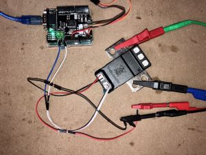
First of all, set up your Arduino Uno and CAN bus shield.
Once the data is coming in over CAN, we can write a simple program to read the current value from the IVT-S.
There could be a lot of messages coming back on the CAN bus, so we specify a "mask" and "filter" for the CAN message IDs we are interested in. CAN bus message IDs are 11 bytes long, so we will specify a mask of 0x7ff (which is 11111111111 in binary). Using an MCP2515-based shield, we can set up to six different filter IDs. According to the Isabellenhütte IVT-S data sheet, the message ID of the "Current" reading from an IVT-S is 0x521, so we will specify that as the filter.
Once those parameters are set, the data should come in over CAN bus every 20ms at 1Mb/s.
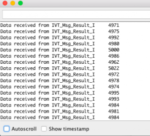
The tricky part is that the current measurement comes from the the IVT-S as a buffer of four byte values in big endian order. We have to re-assemble these bytes to get the numerical current value (in mA). Once that's done, we get nice, readable numerical values on the serial console.
Here's the code:
// IVT-S meter using CAN bus shield
// electric_dart 2020

#include <SPI.h>
#include "mcp_can.h"

// the cs pin of the version after v1.1 is default to D9
// v0.9b and v1.0 is default D10
const int SPI_CS_PIN = 10;

MCP_CAN CAN(SPI_CS_PIN);                                    // Set CS pin

unsigned char len = 0;
unsigned char buf[8];

void setup() {
    // Set your Serial Monitor to 115200 baud
    Serial.begin(115200);

    // Initialise the CAN bus
    while (CAN_OK != CAN.begin(CAN_1000KBPS)) {            // init can bus
        Serial.println("Failed to initialise CAN bus. Retrying...");
        delay(100);
    }
    Serial.println("CAN bus initialised.");

    /*
        set receive mask
    */
    CAN.init_Mask(0, 0, 0x7ff);                         // there are 2 masks in mcp2515, you need to set both of them
    CAN.init_Mask(1, 0, 0x7ff);                         // 0x7ff is '11111111111' in binary, so we are checking 11 of the CAN message ID bits

    /*
        set receive filter
    */
    CAN.init_Filt(0, 0, 0x521);                          // there are 6 filters in mcp2515
    CAN.init_Filt(1, 0, 0x521);                          // 0x521 is the CAN message ID for IVT-S Current value
    CAN.init_Filt(2, 0, 0x521);
    CAN.init_Filt(3, 0, 0x521);
    CAN.init_Filt(4, 0, 0x521);
    CAN.init_Filt(5, 0, 0x521);

}

void loop() {
    if (CAN_MSGAVAIL == CAN.checkReceive()) {         // check if data coming
        CAN.readMsgBuf(&len, buf);    // read data,  len: data length, buf: data buf
        unsigned long canId = CAN.getCanId();

        if (canId == 0x521) {
          Serial.print("Data received from IVT_Msg_Result_I");
          Serial.print("\t");

          // Convert individual big endian byte values to actual reading
          long reading = (buf[2] << 24) | (buf[3] << 16) | (buf[4] << 8) | (buf[5]);
          Serial.println(reading);
        }
    }
    // Refresh every 250ms
    delay(250);
}

