OEM Inverter OI modification
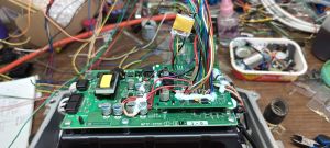
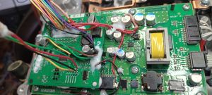
This page describes control of Mitsubishi rear inverters with OI brain board V3.
Transistor signals are open collector.
No fault signal found yet...
Resolver is connected directly with OI.
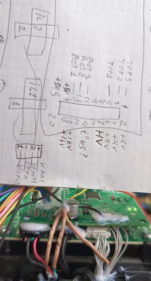
HV signal is read connected to the yellow wire.
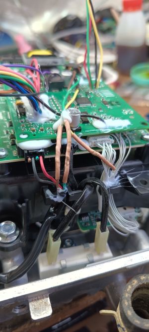
The HV signal must go through a divider of two 3.3 kOhm resistors. Otherwise, the level becomes too high after about 330 volts and the v3 board is not able to fully measure. I soldered two resistors directly at the input of the measurement wire, through one signal itself, and the second from the entry point to the ground.
recorded 127 kW on the wattmeter! Picture shows 0.1 uf condenser mounted on the shutter and the GND. This gives a delay in switching on the contactor and it OVERCAME the problem of arbitrarily turning on the contactor for a fraction of a second when 12 volts are supplied.
 |
 |
 | |
 |
 |