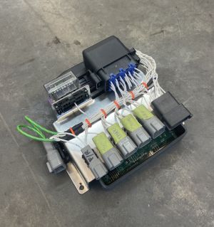
Pre-wired zombieverter interface

the core ev control system across different builds is majorly the same:
- throttle input
- start/fwd/rev input
- contactor control
- inverter control
- charger control
- bms interface
- gauges/displays/data
why build custom wiring harness when we can standardized the main system with a pre wired ev system interface for the zombiverter vcu
hence the "pre wired zombie interface"
consolidating the zombieverter VCU, ev 12v power distribution(fuse, relays, grounds), CAN BUS lines, along with the fundamental inputs and outputs
hardware:
- metal tray acts as a base for everything to mount to
- zombieverter VCU is enclosed in a custom 3d printed case
- OBD-ii port
- little fuse 18pin pdm enclosure with Metri-Pack 280 pins
- deutsch connectors
The little fuse pdm enclosure houses 2 relays and 5 fuses:
- switch 12v ign relay + fuse
- generic output relay + fuse
- zombieverter 12v supply fuse
- inverter 12v supply fuse
- charger/bms 12v supply fuse
the OBD-ii port is on the zombieverters transmits data only:
- CANBUS 2
- 12v+
- GND -
parts list:
Deutsch connectors:
- DT04-4P 4-Way
- DT04-6P 6-Way
- DT04-12PA 12-Way
- 0460-202-16141 Pin
- DTP04-2P 2-Way (for power)
- 0460-204-12141 Pin
OBD-II:
- molex 51115-1601
- pins 50420-8000
mounting:
- sheet metal tray
- zombieverter vcu case
- Deutsch 1011-310-0205 Mounting Clip
PDM:
- PDM31002ZXM
- wire seal 829-15324982
- terminals 12162595-L
- relay 303-1AH-S-D1-12VDC
- mini fuse
connections:
POWER 2 pin connector:
- 12V +
- GND -
INVERTER 6 pin connector:
- 12v
- gnd
- ign (switch via relay)
- CAN
- CAN
BATTERY 12 pin connector:
- 12v
- gnd
- ign (switched via relay)
- CAN H
- CAN L
- pre charge contactor (low side switching)
- positive contactor (low side switching)
- negative contactor (low side switching)
- prox pilot
- charge port spoof
SWITCHES 4 pin connector:
- forward
- revers
- on
- start/ign
THROTTLE 4 pin connector:
- gnd
- sig
- sig
- 5v
chademo 6 pin connector:
- gp out 2
- gp out 3
- GP12vIN
- CAN H 3
- CAN L 3
- gnd
AUX 4 pin connector:
- CAN 2 H
- CAN 2 L