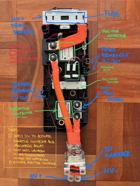
Nissan Leaf Precharge Unit
All generations of Nissan Leaf came with a similar precharge unit design. The design is based on two Panasonic contactors, one precharge resistor, and one precharge relay.
General Purpose
The purpose of a precharge circuit is to avoid an onrush of current when an HV circuit is closed. If you consider the sheer amount of energy sitting in a fully charged EV battery, it's pretty clear that when you 'switch the motor on', there will be a moment when suddenly the energy rushes through, and this could lead to damage.
Typically, 'switching on' an HV circuit involves closing a contactor. A contactor is basically a switch which can handle very high currents, and is activated by applying a bit of low voltage current to a device which will push the switch closed. When the contactor is open, no current can flow, when it is closed, high currents can flow.
Unfortunately, because the voltage on the battery side of a contactor is so high (typically 300V+), the voltage on the other side is 0V, and the resistance in the circuit is so low, the moment before actual contact is made, the two sides of the switch will be close enough that electricity can jump through the air from the one end to the other. This is called 'arcing' and is bad because it can fuse the contactor shut, resulting in it never switching off.
The strategy that a precharge circuit adopts to avoid this situation is to have a bypass circuit, which has a very high resistance (actually, it has a resistor in it). This circuit is typically closed by means of a relay, which is like a contactor, but for lower currents.
What we do is, we complete the precharge circuit first. This allows current to trickle through the whole circuit (it's a trickle because of the resistor), gradually bringing up the voltage on the inverter end of the HV circuit. When the voltage on both ends of the circuit are similar, then the voltage on both ends of the contactor terminals will be similar, and we can safely close the contactor without arcing.
Nissan Leaf Precharge Circuit Use Cases

These contactor boxes are great because they are an all-in-one package that comes pre-wired and can handle a relatively large amount of power. You don't have to do any fancy CAN framing or specific sequencing, just provide 12v at a specified location and you're good to go.
The contactors and relay are controlled by means of 6 pins in a connector on the corner of the unit (top right in the picture to the right). Each component is controlled by two pins. One pin permanently grounded. If you provide 12V+ to the other pin, the relevant component will be activated until you remove 12v+.
Note - because these contactors are rated for 500V/200A, they might not be suitable for high performance applications. Make sure to check what your expected current loads will be!
Ratings
The precharge resistor is 30 ohm (+/- 5%) rated and is apparently rated for 40w continuous. It can handle 15 amps for short periods, however.
The precharge relay (Panasonic AEV6501C) doesn't have a datasheet anywhere, but it's fine for at least 15 amps for short periods and 400 volts.
The positive and negative contactors (Panasonic AEV6505A/AEV6506A) are rated for 200a continuous and 500v. Coil voltage 11-20v.
Wiring

