Simo, if you haven't already, read
this post of mine where I summarize the decision points on modding my OEM EV. The MB B250e has the same infrastructure as our RAV4s.
Currently, I'm about USD $800 into adding CCS to my GEN2 RAV4 EV (I track expense and shipments with a spreadsheet per project) . . . thinking to:
- Replacing the Toyota charge port with BMW i3 CCS port (bought one with harness at a bargain price, couldn't resist)
- Install a Damien ZombieVerter to talk to and drive a BMW i3 LIM (speaks CCS to the EVSE)
- A pair of BMW i3 135A-class contactors (to switch in the charge port CCS DC to the car's existing HV bus, with the correct 15.3 ohm oil impedance to keep the LIM happy)
- An IVT-S shunt to provide current/voltage info to the ZV
- A voltage-to-current sensor board to make the LIM happy
I have all the above, except the ZV, which is pretty much the last big-ticket item; all the rest is fiddly-bits.
[if the
AR7420-based CCS EVCC becomes more mature reasonably quickly, I may ditch the LIM and its voltage-sense board (and maybe its contactors), and the ZV, and go with that cleaner-sheet controller, but the LIM path is well-trod and repeatable.]
That, plus a bunch of HV wire, is the hardware end of things. Currently, I'm planning to tap the battery pack the same way that the CHAdeMO add-on kit does: at the front of the pack, install extension studs where the drive unit inverter cables connect to the pack. The easy-looking way to push CCS DC would be to connect to the existing OBC's output lines in the small HVJB that's bolted on the right side (left, as you look under the hood) of the OBC, but for 125A/50kw we require 2 AWG wires to the pack, minimum, and the existing wiring will not suffice, nor can where they connect to the pack be gracefully uprated for 125A. So, separate DCFC wiring and therefore its own HVJB. That HVJB would ideally be underhood or very close, but there's not a lot of room under there. The CHAdeMO got around that by fabricating a fairly elaborate support in place of the plastic "engine cover", quite a nice bit of work. I'm not above stealing a good idea, but I haven't decided on the HVJB location yet.
The CHAdeMO kit requires you put the car in "Ready" mode first, which has the HV rail hot -- the drive unit's inverter leads hot -- and then their box pushes current to the pack. I intend to try to do that a bit more elegantly -- that's the goal, anyway. But I do want to allow the Tesla bits to continue to run the BMS and AC charging show, which means I don't want to go full clean-sheet and take over control of everything, and thereby lose the Toyota integration features.
That's why I bought a spare OBC (and, later, a HVJB so I could confirm where some of the OBC's unused-in-the-RAV4 connections connected, and what they did, and it was cheap to buy and fun to trace) and just today got my second order of X042 (LV & Signals) harness parts from Mouser: I can now build the plug-in breakout harness for X042, and begin data collecting. Other people have this information already, but they're not sharing it publicly, so I'll do it the hard way. So . . . I created a Wiki article for each, and Johannes let me, even though it's unlikely that EV folk are going to repurpose these GEN1 Tesla parts, when the GEN2 & 3 are so much better.
Which leads me -- finally -- to this:
I was contemplating if adding the HVJB would be beneficial in addition to adding the Tesla Charge port . . .
The Tesla Model S GEN1 Rear HVJB is just too big. IMO. Yeah, I can cut off the mounting ears but it still is way too large for two contactors, two fuses, the IVT-S shunt and the voltage sense board. Its biggest issue (pun intended) is that it's not rectangular in height, which is a problem if you're trying to fit it under the hood in
addition to what's already there.
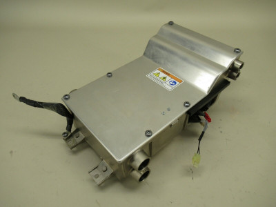
- Tesla Model S GEN1 Rear HVJB
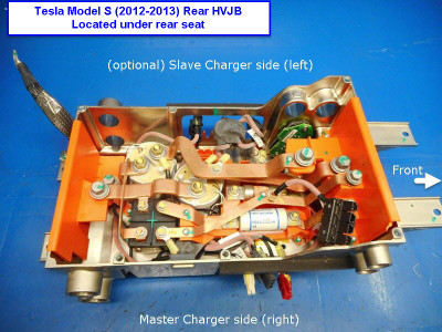
- Tesla Model S GEN1 Rear HVJB
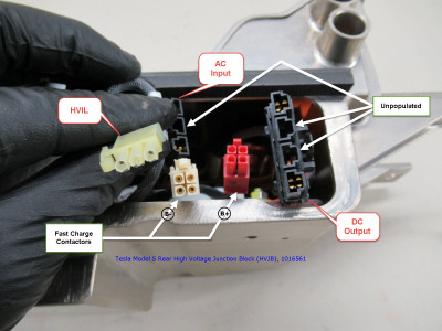
- Tesla Model S GEN1 Rear HVJB
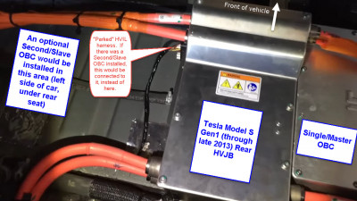
- Tesla Model S GEN1 Rear HVJB
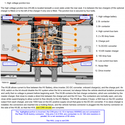
- Tesla Model S GEN1 Rear HVJB
I really think that making or buying a different box would be better than trying to rework this one. There's a lot going on in that space, Tesla did a masterful packaging job, but it doesn't adapt well. Maybe repurpose a GEN2
Front HVJB . . . I'll probably just roll my own.
I'm not interested in trying to make a Tesla charge port work. Supercharger stations are going public for all in the US (CCS adapters are built-in to the VC SCs) so I'm going CCS. The nozzle locking will work with the BMW i3 LIM and BMW charge port (or other CCS1 charge ports) and that's enough for me.
---
My new logic analyser won't arrive until next week -- no, I didn't buy a
Salae, but I've got DueCAN parts all on my side workbench. My RAV4 got hit last month (only a front bumper, light RF fender scrape, and a small bump under the driver's door handle) and is STILL at the body shop -- they are short-handed. They have been doing bodywork for me for years and do the best work of any body shop I've used in my life, so I cut them some slack, but it means that there's not a rush for me to get these fiddly bits done right NOW, I can wait another week.
---
Sidebar: I've got a completely separate project on which I need to do week-long monitoring of DC low current using a clamp transducer -- datalogging. The Good Stuff is like Fluke 289, but we're talking well above USD$500, it'll only do ~900 events in memory, and requires another $200 for an IR<->USB cable and software to do data transfer and/or continuous logging to a PC using their software. Oh, and the clamp transducer. Ridiculous money for a one-time datalogging project.
I figured to cheap-out and tackle it piecemeal. I bought a
VC8145 for $200 after tax, via Amazon. It's a cheap bench DMM but also 4.5 digits, 82000 count, and the supposed ability to datalog to a PC via an RS-232 interface.
Picked up a cheap low-current DC ma to mv transducer, too.
The VC8145 has been around for
years and is a known animal. I thought I knew what I was buying. It showed up on my doorstep today, and within four hours, I packed it up and am mailing it back.
1) The RS-232 interface is opto-isolated (good!) which means it requires power from the RS-232 host (um . . . ) but most "serial hosts" these days are USB<->RS-232 dongles, and most of them also can't provide enough power to fire up the VC8145's client interface circuit. I tried three dongles I have around, ONE of them supplied enough current.
2) It has no internal storage, so all logging has to happen on the PC. OK, I knew that. But! you're supposed to use the included software, which is supplied on a mini-CD (remember those?) and which also is Rev. 1 and won't run on anything newer than WinXP. Ahhhh . . . OK . . . I have a WinXP VM handy, so I install the software . . . and . . . the display slowly, over the space of a minute, starts twitching, with various segments turning off & on, eventually culminating in the unit locking up.
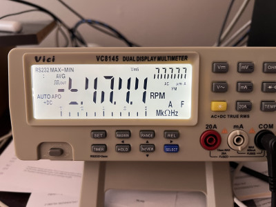
- VC8156 locked up
3) The WinXP software limitation is also well-known, so I tried two other apps that do work with the VC8145 (I liked "Test Controller", it works with a LOT of different multimeters), and . . . same.
So, I packed it back up in its cute box, printed off the Amazon return QR code, and I'll drop it at the local UPS Store tomorrow.
That was pretty much all day.
Then, I spent a couple hours looking for an alternative . . . and I'm right back to buying a Fluke 289 (or 287, 189, 187, or 87 IV), all of which can stream data to a PC . . . using a $80 IR<->USB cable and the aforementioned "Test Controller" software, bypassing the expensive FlukeView Forms version.
I think I found a local used one, two actually: one for $325 that looks pretty well used, and another that appears new for $400. Plus the IR cable. Ugh.
Still hoping that cheap Chinese low current transducer works . . . when it shows up next week.
---
Lots of time wasted on not-strictly-project-related work, just to get the bench ready. Sheesh. I don't know why I typed that all here, I guess I just wanted to vent.
