IT WORKED!!!!
I guess either I only programmed the bootloader before or the charger file but regardless I was finally able to configure the charger.
Thank you all for your help!!
But now, I connect everything up and my EVSE shows it's connected and "charging", but the charger modules are not turning on (no red lights). The spot value for "state" shows "WaitStart".
I don't have external CAN enabled, but I read something in the troubleshooting I need to confirm the CAN bus is properly terminated via closing the solder jumper next to R1 under the WIFI module for V5aB2. I looked under my Wifi module and see R1, but not necessarily any jumper. Am I missing this? Also where would I measure on the board between CAN H and L to confirm 120 Ohms or does this even apply?
Tesla Gen 2 Charger configuration help
-
Bratitude

- Posts: 1156
- Joined: Thu Jan 02, 2020 7:35 pm
- Location: Canada
- Has thanked: 246 times
- Been thanked: 469 times
- Contact:
Re: Tesla Gen 2 Charger configuration help
If your using can then yes, but but charger just operating stand alone, that won’t apply.
How and what do you have wired? what plug are you using, what resistance is the pilot pin?
How and what do you have wired? what plug are you using, what resistance is the pilot pin?
https://bratindustries.net/ leaf motor couplers, adapter plates, custom drive train components
-
spiff
- Posts: 75
- Joined: Thu Jul 14, 2022 8:44 pm
- Location: Toronto
- Has thanked: 4 times
- Been thanked: 6 times
Re: Tesla Gen 2 Charger configuration help
Here's my setup:
Tesla EVSE with adapter to J1772 plug.
Plug is wired to SimpCharge and then to VeroBMS (similar to Simp BMS) for CP and PP.
I have the 12V charge enable signal from the BMS/SimpCharge wired to the 2 Tesla Charger 12V in connections (A3, B1)
Power wires from plug go to charger via fuses
For testing, I've also spliced the PP and CP to go from the plug directly to the Tesla Charger connections (B5, B11) and given the Charger 12V directly (not from BMS). So I can see the wifi go on, but nothing else happens.
Currently, when the plug is connected and the EVSE thinks it's on, the PP to ground measures 0 resistance.
-
tom91

- Posts: 2962
- Joined: Fri Mar 01, 2019 9:15 pm
- Location: Bicester, Oxfordshire
- Has thanked: 330 times
- Been thanked: 847 times
Re: Tesla Gen 2 Charger configuration help
Not possible, you cannot splice charge point signals.
Please provide the parameters of your charger settings.
Please provide pictures of your setup.
-
spiff
- Posts: 75
- Joined: Thu Jul 14, 2022 8:44 pm
- Location: Toronto
- Has thanked: 4 times
- Been thanked: 6 times
Re: Tesla Gen 2 Charger configuration help
Again Thank you for the support!
Here's my charger settings:
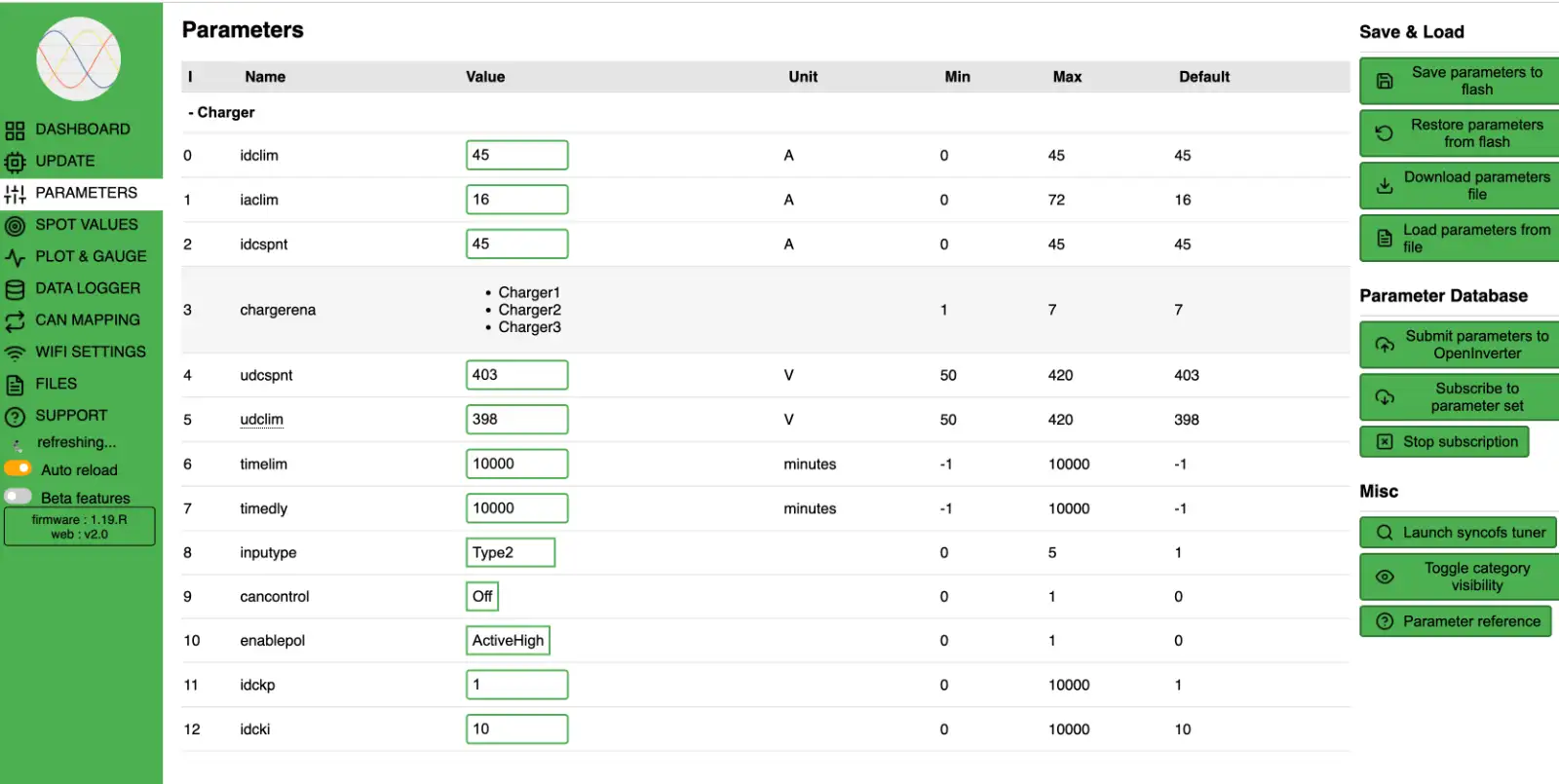
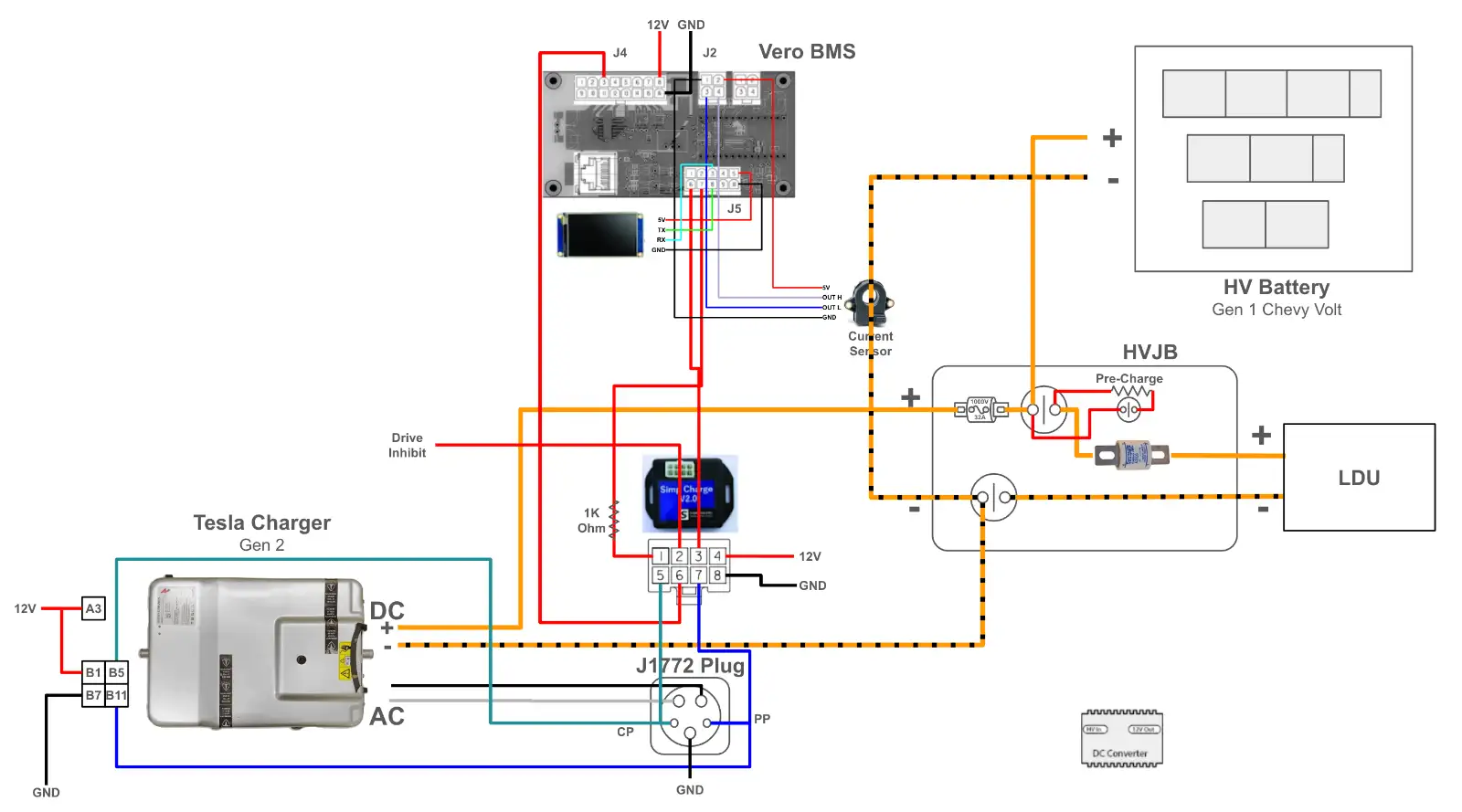
Here's the charger related items of my setup. If I can't splice the CP and PP signals, what is the easiest way to connect the simpcharge to the Tesla Charger connections B5 and B11?
Here's my charger settings:
Here's the charger related items of my setup. If I can't splice the CP and PP signals, what is the easiest way to connect the simpcharge to the Tesla Charger connections B5 and B11?
-
tom91
- Posts: 2962
- Joined: Fri Mar 01, 2019 9:15 pm
- Location: Bicester, Oxfordshire
- Has thanked: 330 times
- Been thanked: 847 times
Re: Tesla Gen 2 Charger configuration help
Not. The Tesla charger needs to be permanently powered B1.
The BMS can be used to prevent charging starting by not providing 12V to A3.
The Charger will request HV by grounding pin A6 HV Enable - this is required for timing reasons, I do not believe you can have HV permanently connected, but it has been over 8 years since I wrote the original Tesla Charger control code.
https://openinverter.org/wiki/Tesla_Mod ... N2_Charger
Also add a ground to the charger case.
PARAMS
They do not look right to me, have a review of the wiki and change them to suit your setup https://openinverter.org/wiki/Tesla_Mod ... 5_Software
You can try the following to check you charger is working internally. Wire up just your charger to the charge port and leave B1 and A3 tied to 12V permanently.
Configure the input type correctly to Type 1.
Then plug in your type 1 and monitor the spot values for the proximity and pilot. Also the Leds should come on on your power modules and power modules spot values should populate.
-
spiff
- Posts: 75
- Joined: Thu Jul 14, 2022 8:44 pm
- Location: Toronto
- Has thanked: 4 times
- Been thanked: 6 times
Re: Tesla Gen 2 Charger configuration help
Thanks Tom,
I did ground the charger case to the chassis previously but didn't show it in the diagram.
Thanks for the tip on B1 vs A3.
The piece I'm still not clear on is pin A6 HV Enable. I've tried checking the documentation and searching the forum and came back empty.
Also, I did look at the guide to setup my parameters. I thought the difference between type 2 and type 1 inputs is that type 1 is fixed at 40A whereas type 2 will take any current level.
I've tried permanently attaching B1 and A3 to 12V and the wifi module turns on, but none of the power modules light up. Is this again related to the A6 HV Enable?
-
tom91
- Posts: 2962
- Joined: Fri Mar 01, 2019 9:15 pm
- Location: Bicester, Oxfordshire
- Has thanked: 330 times
- Been thanked: 847 times
Re: Tesla Gen 2 Charger configuration help
Yes, and only the charger to the Type 1 inlet and then insert the EVSE. All while checking your spot values to see if the plug gets detected propperly.
-
spiff
- Posts: 75
- Joined: Thu Jul 14, 2022 8:44 pm
- Location: Toronto
- Has thanked: 4 times
- Been thanked: 6 times
-
tom91
- Posts: 2962
- Joined: Fri Mar 01, 2019 9:15 pm
- Location: Bicester, Oxfordshire
- Has thanked: 330 times
- Been thanked: 847 times
Re: Tesla Gen 2 Charger configuration help
HV enable, this output comes on in the right time in the charging process during the waking of the power modules. When testing I believe there was a timing requirement between HV and AC power application to make the power modules happy.
-
spiff
- Posts: 75
- Joined: Thu Jul 14, 2022 8:44 pm
- Location: Toronto
- Has thanked: 4 times
- Been thanked: 6 times
Re: Tesla Gen 2 Charger configuration help
Thanks again Tom,
So here's what I did:
- Connected pin A6 on the charger to ground
- Connected the CP directly to B6 and PP to B11 (no longer spliced)
- Changed input type on the charger config to Type 1
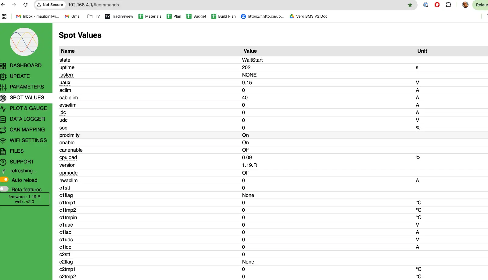
Then I connected AC and DC voltage to the charger and then plugged in the EVSE. Unforunately, the power module LEDs still remain unlit and my spot values are the following:
Is my charger bad after all of this?
So here's what I did:
- Connected pin A6 on the charger to ground
- Connected the CP directly to B6 and PP to B11 (no longer spliced)
- Changed input type on the charger config to Type 1
Then I connected AC and DC voltage to the charger and then plugged in the EVSE. Unforunately, the power module LEDs still remain unlit and my spot values are the following:
Is my charger bad after all of this?
-
tom91
- Posts: 2962
- Joined: Fri Mar 01, 2019 9:15 pm
- Location: Bicester, Oxfordshire
- Has thanked: 330 times
- Been thanked: 847 times
Re: Tesla Gen 2 Charger configuration help
I do not know how the latest verson works it is still in wait state for some reason. and in op mode off. There are also more spotvalues than just those you show.
Your EVSE Lim shows 0, do you have a dumb EVSE and not a Tesla one? Or can you set your eve to a dumb version as the Tesla EVSE does not talk "type 1" pwm but a digital tesla protocol.
Your EVSE Lim shows 0, do you have a dumb EVSE and not a Tesla one? Or can you set your eve to a dumb version as the Tesla EVSE does not talk "type 1" pwm but a digital tesla protocol.
-
spiff
- Posts: 75
- Joined: Thu Jul 14, 2022 8:44 pm
- Location: Toronto
- Has thanked: 4 times
- Been thanked: 6 times
Re: Tesla Gen 2 Charger configuration help
I configured the Tesla evse to work with any car previously, then tried again in “compatibility” mode. Unfortunately still no luck.
Previously, when I plugged it in, the evse turned blue initially (ready to charge) then switched to a moving green (charging). But no change on the charger itself. Now, it only stays in the blue state (ready to charge).
Again do I need to measure resistance or some other diagnostic checks to confirm?
-
tom91
- Posts: 2962
- Joined: Fri Mar 01, 2019 9:15 pm
- Location: Bicester, Oxfordshire
- Has thanked: 330 times
- Been thanked: 847 times
Re: Tesla Gen 2 Charger configuration help
Fact EVSE Lim or AC Lim is 0 leads me to believe there are issues with your EVSE or charge port wiring.
Did you ground your charge port to the charger?
Did you ground your charge port to the charger?
-
spiff
- Posts: 75
- Joined: Thu Jul 14, 2022 8:44 pm
- Location: Toronto
- Has thanked: 4 times
- Been thanked: 6 times
Re: Tesla Gen 2 Charger configuration help
Not to the same grounds but both are grounded to the chassis.
-
spiff
- Posts: 75
- Joined: Thu Jul 14, 2022 8:44 pm
- Location: Toronto
- Has thanked: 4 times
- Been thanked: 6 times
Re: Tesla Gen 2 Charger configuration help
Hi Tom et al,
I've been away on vacation so I haven't had the time to dig further into this.
Last night I was trying a few things out and verified all the wiring and connections and still was stuck on getting the Tesla EVSE to start charging (ie. providing the AC input into the OBC).
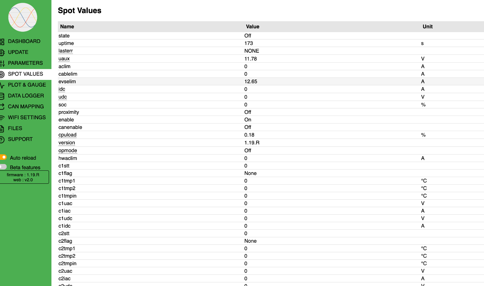
So I finally put the wiring back to incorporate the SimpCharge. Even though you mentioned you can't splice the PP and CP signals, I did and when I plugged everything in, the EVSE started applying AC power to the OBC. I validated this at the AC input connector.
But the red lights for each power module in the OBC were not lit, no current was coming out of the HV DC connector.
Here are the Spot values showing the EVSE on:

I don't think I ever got an answer, but what is the right way to wiring in the SimpCharge to the OBC using the Openinverter control board? I'm not using CAN. Is there a way I can confirm the OBC is actually functional? It feels like this wiring config is still not correct so I want to rule this out or even at least run the charger in manual mode to see if it turns on but somehow in that config it doesn't let the EVSE turn on.
Thanks again in advance!
I've been away on vacation so I haven't had the time to dig further into this.
Last night I was trying a few things out and verified all the wiring and connections and still was stuck on getting the Tesla EVSE to start charging (ie. providing the AC input into the OBC).
So I finally put the wiring back to incorporate the SimpCharge. Even though you mentioned you can't splice the PP and CP signals, I did and when I plugged everything in, the EVSE started applying AC power to the OBC. I validated this at the AC input connector.
But the red lights for each power module in the OBC were not lit, no current was coming out of the HV DC connector.
Here are the Spot values showing the EVSE on:
I don't think I ever got an answer, but what is the right way to wiring in the SimpCharge to the OBC using the Openinverter control board? I'm not using CAN. Is there a way I can confirm the OBC is actually functional? It feels like this wiring config is still not correct so I want to rule this out or even at least run the charger in manual mode to see if it turns on but somehow in that config it doesn't let the EVSE turn on.
Thanks again in advance!
-
tom91
- Posts: 2962
- Joined: Fri Mar 01, 2019 9:15 pm
- Location: Bicester, Oxfordshire
- Has thanked: 330 times
- Been thanked: 847 times
Re: Tesla Gen 2 Charger configuration help
None.
The charger needs to be setup and wired to properly turn on the EVSE.
Note the opmode showing off for each of the previous screenshots.
The spotvalue "evselim" will populate once a correct Control Pilot signal is detected.
So the charger does the following:
State: Off = Enable is high + Proximity is detected + Proximity cable limit verified => State:WaitStart = timedly has passed
Try changing timedelay to 0, AS PER WIKI https://openinverter.org/wiki/Tesla_Mod ... 5_Software
Stop messing around with the wiring and do as instructed.timedly
The default value is -1 but this results in the charging waiting forever. You need to set this to 0 (or more) for the OBC to work.
-
spiff
- Posts: 75
- Joined: Thu Jul 14, 2022 8:44 pm
- Location: Toronto
- Has thanked: 4 times
- Been thanked: 6 times
Re: Tesla Gen 2 Charger configuration help
Understood and acknowledged. I don't take this lightly and very much appreciate yours and everyone's time and willingness to contribute. I just couldn't figure out why my EVSE wasn't turning on so I needed to revert to ensure I could verify the EVSE works and does produce current and it does!
Yes, mine was already set to 10000 as the instructions said "0 or more", but thank you. I will set to 0 to confirm.tom91 wrote: ↑Fri Aug 01, 2025 2:35 pm Try changing timedelay to 0, AS PER WIKI https://openinverter.org/wiki/Tesla_Mod ... 5_Software
So just to confirm, (and hopefully for the benefit of others reading this), the purpose of the SimpCharge was to control the EVSE. If I remove this, then this will be how the wiring will be configured:
1. CP and PP lines go directly from charging plug to the OBC (pins B5 and B11 respectively)
2. PE goes from charging plug to chassis and GND from OBC (pin B7, and OBC case also grounded here as well as A6)
3. Line and Neutral from charging plug go to AC input on OBC
4. 12V constant goes to OBC B1.
5. 12V signal to turn on from SIMPBMS goes to A3. For testing purposes, I already tried permanently connecting both B1 and A3 to 12V.
Question:
For the SimpBMS, where do I get a signal from the OBC to show AC is present to feed J5 pin 6? Do I even need to populate this? I'm assuming not for isolated testing of the charger above, but just want to confirm since I can't use the SimpCharge at all.
-
tom91
- Posts: 2962
- Joined: Fri Mar 01, 2019 9:15 pm
- Location: Bicester, Oxfordshire
- Has thanked: 330 times
- Been thanked: 847 times
Re: Tesla Gen 2 Charger configuration help
The HV request output from the charger is when it wants to charge. Note this is a grounding output.
-
spiff
- Posts: 75
- Joined: Thu Jul 14, 2022 8:44 pm
- Location: Toronto
- Has thanked: 4 times
- Been thanked: 6 times
Re: Tesla Gen 2 Charger configuration help
So this is Pin A1 on the charger? So this goes to J5 Pin 6 (AC present) on the SimpBMS?
-
tom91
- Posts: 2962
- Joined: Fri Mar 01, 2019 9:15 pm
- Location: Bicester, Oxfordshire
- Has thanked: 330 times
- Been thanked: 847 times
Re: Tesla Gen 2 Charger configuration help
No, J5 needs 5V or 12V, so you need an relay to change from grounding to 12V signal.
-
spiff
- Posts: 75
- Joined: Thu Jul 14, 2022 8:44 pm
- Location: Toronto
- Has thanked: 4 times
- Been thanked: 6 times
Re: Tesla Gen 2 Charger configuration help
I want to ensure I understand this completely:
The OBC pin A6 - AC present is an output signal that shows “GND” when it wants to charge?
So feeding this signal through a relay before it goes to the SimpBMS J5 pin 6 to turn it to 12V positive is what you’re saying it needs?
The OBC pin A6 - AC present is an output signal that shows “GND” when it wants to charge?
So feeding this signal through a relay before it goes to the SimpBMS J5 pin 6 to turn it to 12V positive is what you’re saying it needs?
-
tom91
- Posts: 2962
- Joined: Fri Mar 01, 2019 9:15 pm
- Location: Bicester, Oxfordshire
- Has thanked: 330 times
- Been thanked: 847 times
-
spiff
- Posts: 75
- Joined: Thu Jul 14, 2022 8:44 pm
- Location: Toronto
- Has thanked: 4 times
- Been thanked: 6 times
Re: Tesla Gen 2 Charger configuration help
Sorry, I meant Pin A1 from the OBC is the AC present output.
I've tried the above without connecting A1 from the OBC as I'm right now just trying to get the charger to turn on without connecting it to the BMS. So I think I'm back to the same problem I had before:
12V connected to A3 and B1,
CP and PP connected to B5 and B11,
A6 and B7 connected to ground (along with chassis and PE from J1772 socket).
A1 not connected to anything.
EVSE recognizes it's plugged in, but doesn't start providing AC power.
No charger module red lights come on.
I'm still at a loss trying to understand why the EVSE provides AC power when the CP and PP signals are going through the SimpCharge (spliced) but doesn't provide power when the CP and PP signals are connected directly to the OBC.
If anyone has any thoughts or ideas that I should test or check wiring, I'm all ears.
Thanks in advance!