[WIP] Voltswagen T2 -76
-
johu

- Site Admin
- Posts: 7182
- Joined: Thu Nov 08, 2018 10:52 pm
- Location: Kassel/Germany
- Has thanked: 552 times
- Been thanked: 1913 times
- Contact:
Re: [WIP] Voltswagen T2 -76
That or maybe bus bar your way out. Towards the middle of the motor, then cables?
Support R/D and forum on Patreon: https://patreon.com/openinverter - Subscribe on odysee: https://odysee.com/@openinverter:9
-
Cera
- Posts: 96
- Joined: Thu Feb 10, 2022 10:08 am
- Location: Finland
- Has thanked: 49 times
- Been thanked: 71 times
Re: [WIP] Voltswagen T2 -76
Yeah I'm currently thinking of a set of 90deg busbars towards the middle of the motor, enclosed safely in some 3D printed case, then 50mm2 cables to inverter.  not too worried, I'm sure this can be made to fit somehow.
-
Cera
- Posts: 96
- Joined: Thu Feb 10, 2022 10:08 am
- Location: Finland
- Has thanked: 49 times
- Been thanked: 71 times
Re: [WIP] Voltswagen T2 -76
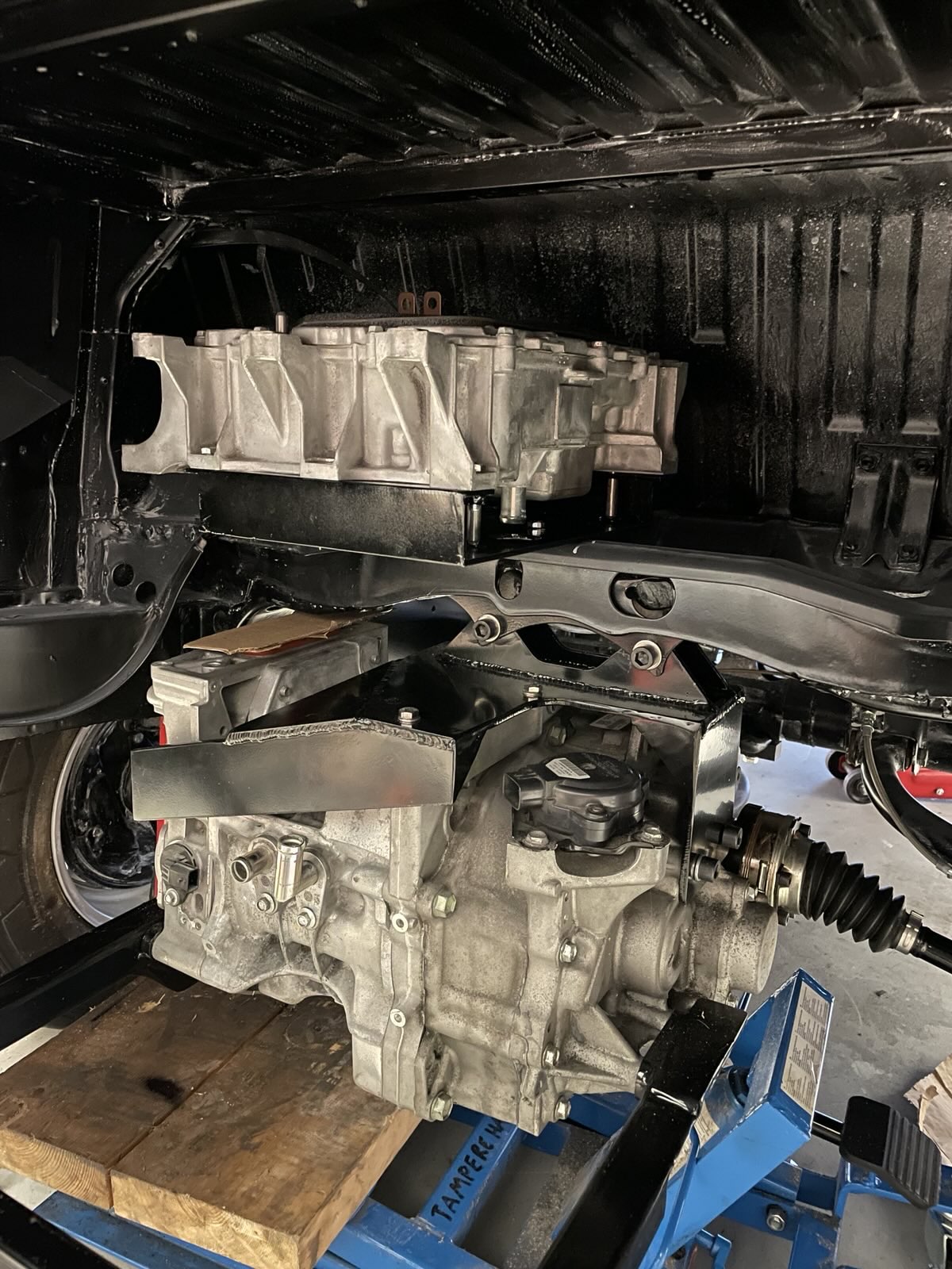
Getting back to this.  Final mount sandblasted, powder coated. Motor has been mounted!

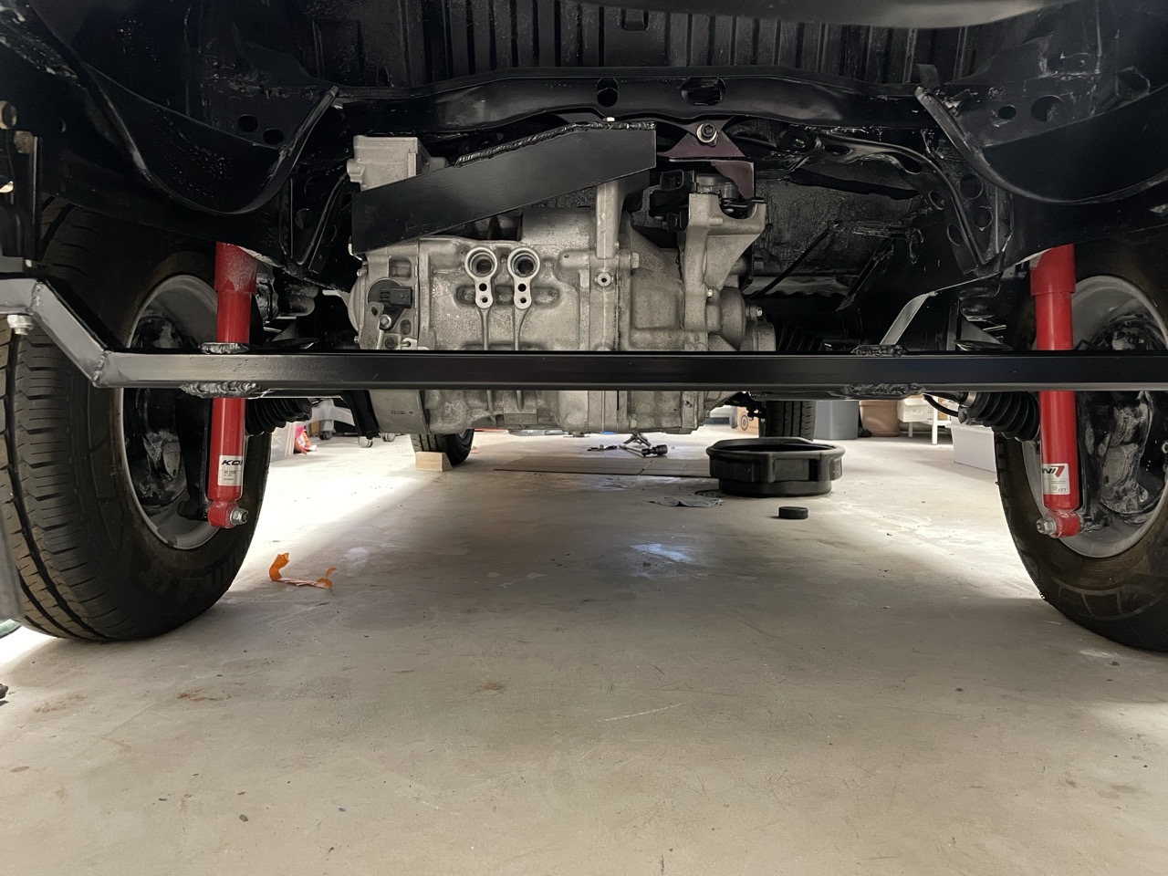
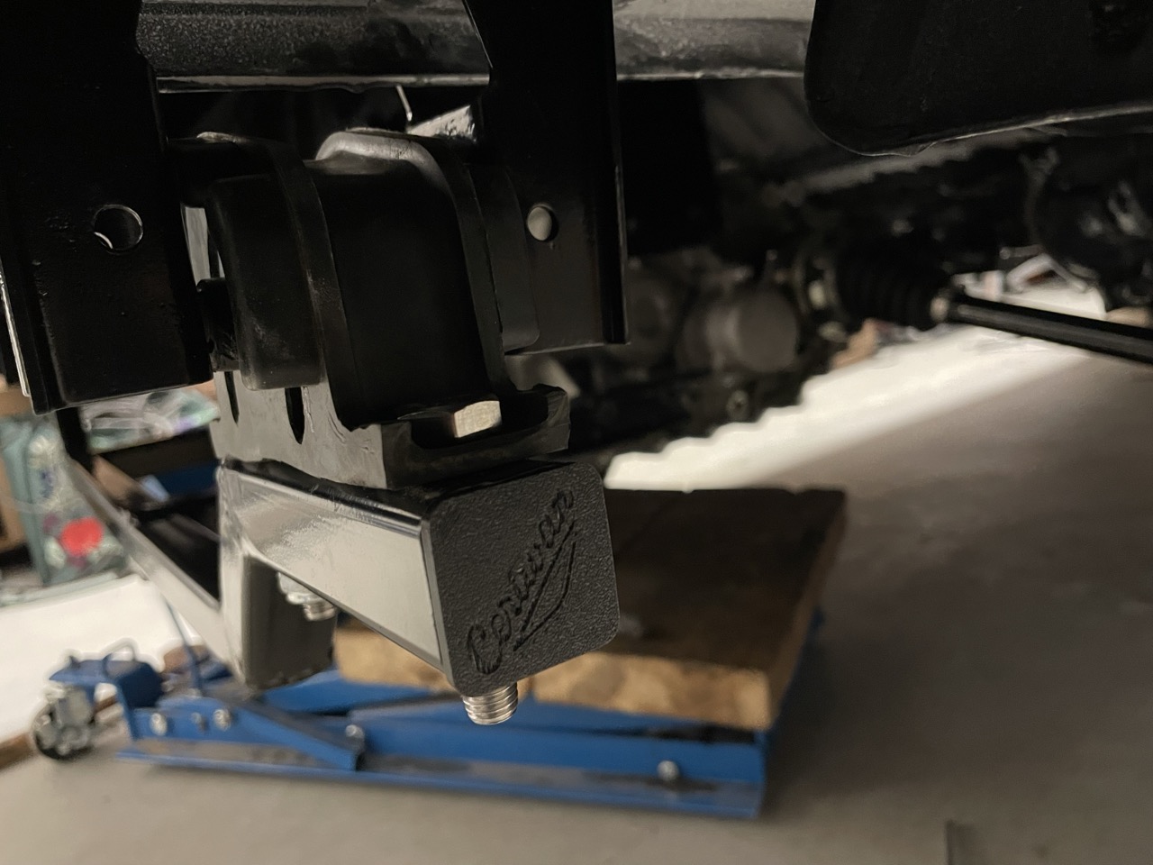
3D-printed some endcaps for the crossbar to keep dirt and dust out. With my own Ceravan logo, of course.
Sketching out mounting places for all the rest of the parts. I think inverter fits well somewhere on the shelf where the gas tank used to be, maybe HVJB next to it. Tesla M3 PCS fits perfectly behind the motor.
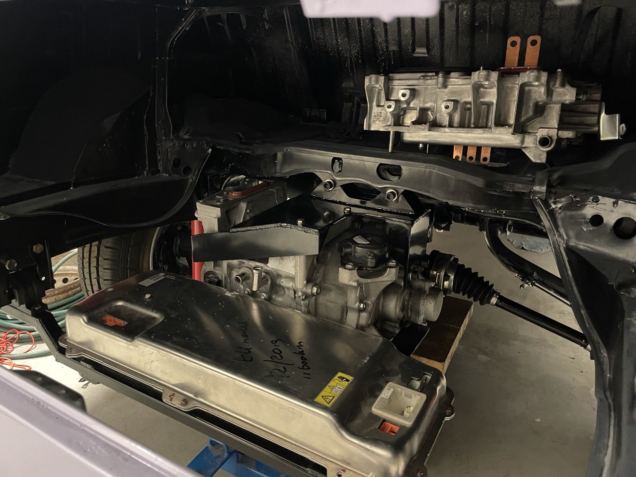
I should start looking into options with the charger etc. I have both the Tesla M3 PCS and the Leaf PDM. Currently leaning on using the M3 PCS with the M3 BMS and other components I got with the pack which as far as I understand saves me from Batman scavenging etc..?
Ah well. Need to study more.
Meanwhile did rest of the brake lines finally, too.
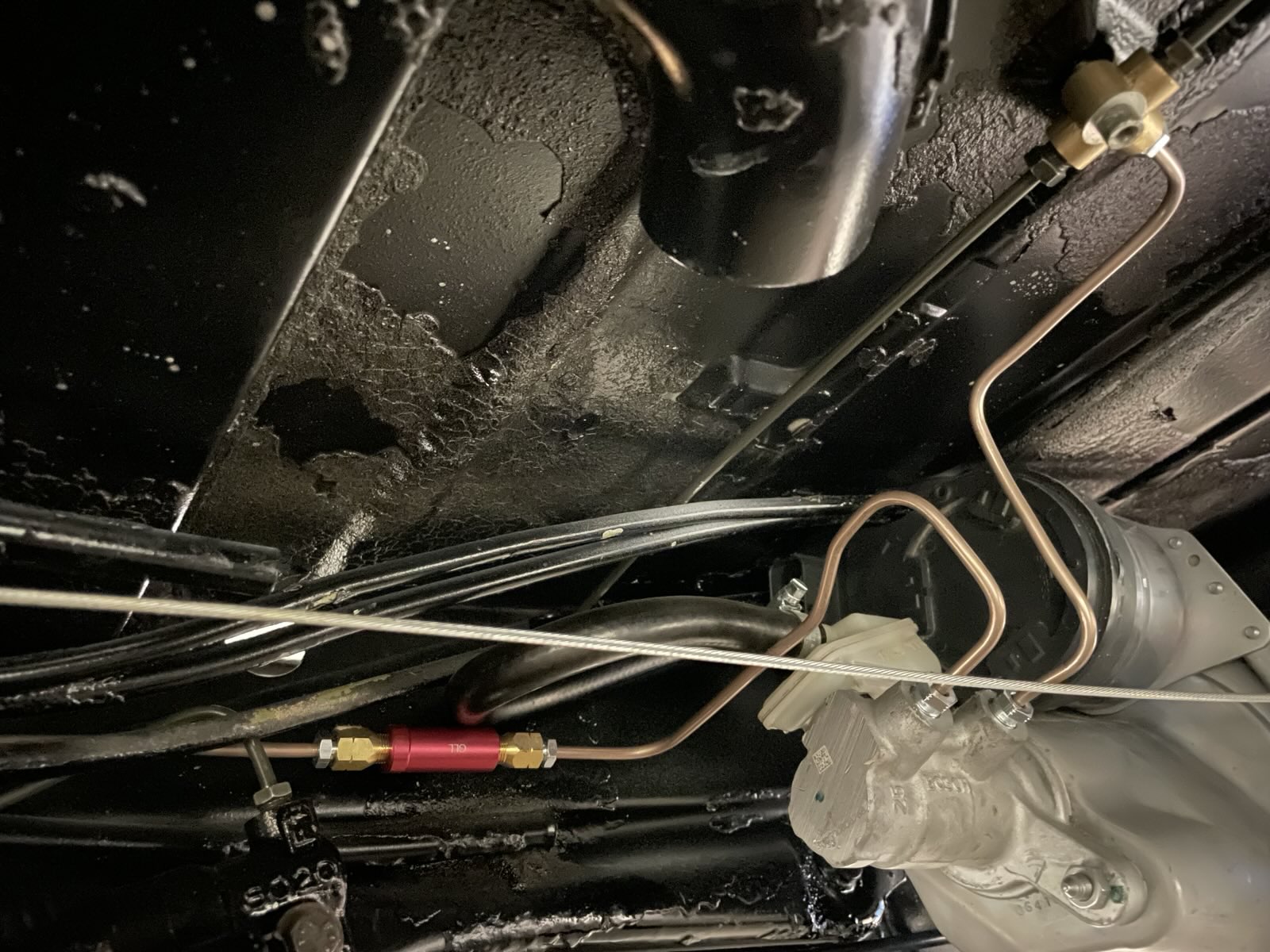
I had some ideas about using pressure switches with T-fittings to do original style brake light switch + brake warning light, but ended up just running the lines straight to the master cylinder at least for now. I don't fancy the idea of extra T-fittings in the lines, weight of the sensors and all the brake fluidy mess if they ever need replacing. Seems easier to install electronic switch somewhere in the linkage for brake lights.
As for the warning light in the dash, which I want just in case, I got a fluid reservoir with the level sensor which I deemed far smarter way of doing that than the pressure switches in the lines. I kind of want to know there's an issue with the brakes *before* the lines have no pressure. I think fluid level sensor in the remote reservoir makes most sense; if there's ever an leak somewhere, hose between the reservoirs gets detached, something horrible, then the reservoir level will go down and light up the warning light while there's still plenty brake fluid in the smaller reservoir on top of the master cylinder etc.
Also, some woodworking in between while waiting for parts.
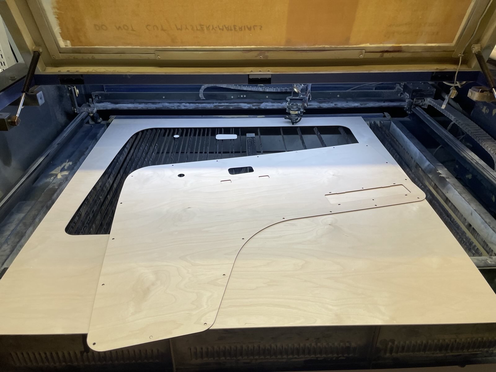
Stain and oil

Mounted for test fit
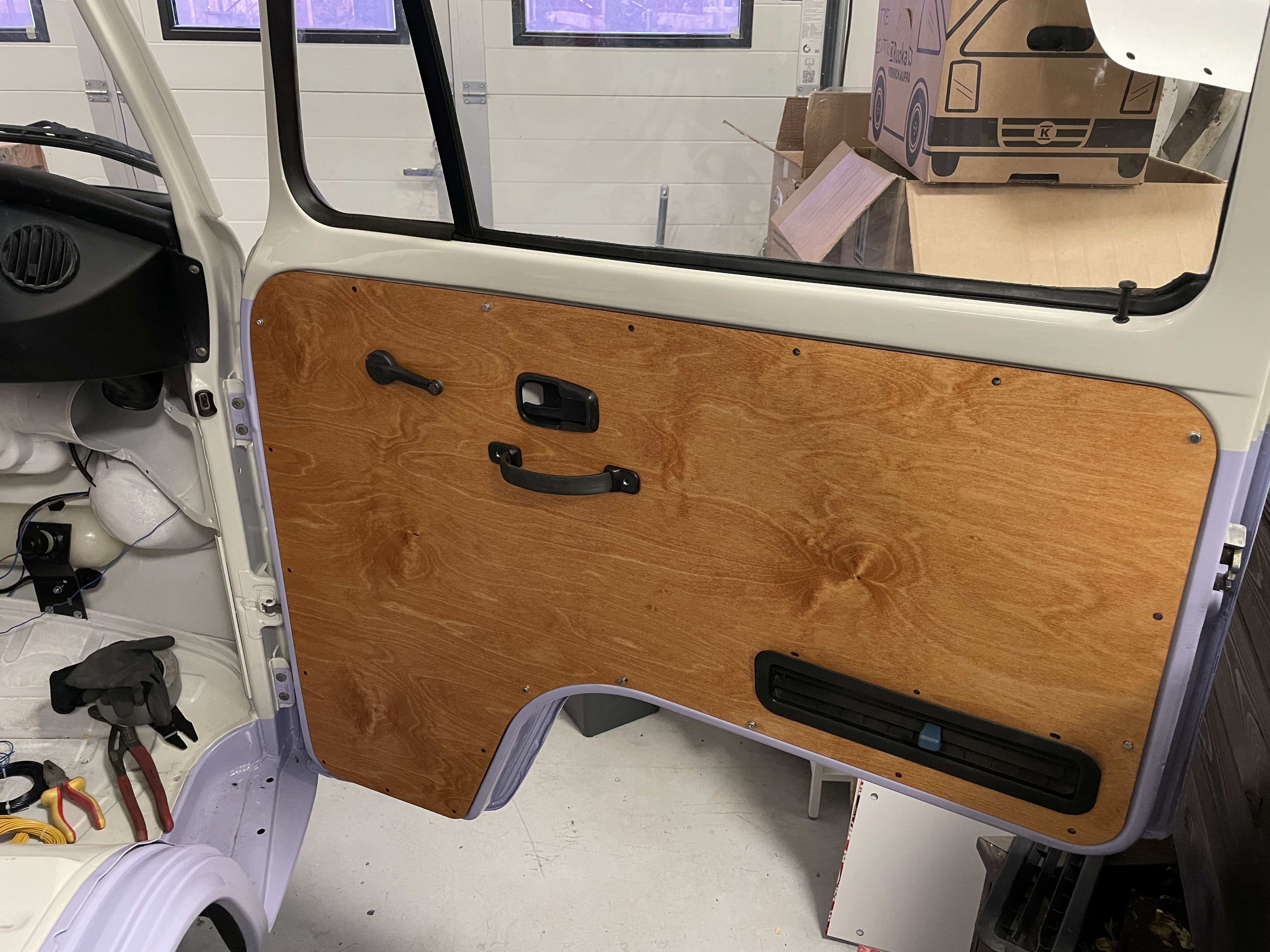
Taking the measurements from the existing rotten door card was very annoying, but I'm really happy with the results.
A few steps onwards again.
 Final mount sandblasted, powder coated. Motor has been mounted!
3D-printed some endcaps for the crossbar to keep dirt and dust out. With my own Ceravan logo, of course.
Sketching out mounting places for all the rest of the parts. I think inverter fits well somewhere on the shelf where the gas tank used to be, maybe HVJB next to it. Tesla M3 PCS fits perfectly behind the motor.
I should start looking into options with the charger etc. I have both the Tesla M3 PCS and the Leaf PDM. Currently leaning on using the M3 PCS with the M3 BMS and other components I got with the pack which as far as I understand saves me from Batman scavenging etc..?
Ah well. Need to study more.
Meanwhile did rest of the brake lines finally, too.
I had some ideas about using pressure switches with T-fittings to do original style brake light switch + brake warning light, but ended up just running the lines straight to the master cylinder at least for now. I don't fancy the idea of extra T-fittings in the lines, weight of the sensors and all the brake fluidy mess if they ever need replacing. Seems easier to install electronic switch somewhere in the linkage for brake lights.
As for the warning light in the dash, which I want just in case, I got a fluid reservoir with the level sensor which I deemed far smarter way of doing that than the pressure switches in the lines. I kind of want to know there's an issue with the brakes *before* the lines have no pressure.
 I think fluid level sensor in the remote reservoir makes most sense; if there's ever an leak somewhere, hose between the reservoirs gets detached, something horrible, then the reservoir level will go down and light up the warning light while there's still plenty brake fluid in the smaller reservoir on top of the master cylinder etc.
Also, some woodworking in between while waiting for parts.

Stain and oil
Mounted for test fit
Taking the measurements from the existing rotten door card was very annoying, but I'm really happy with the results.
A few steps onwards again.
-
alexbeatle
- Posts: 292
- Joined: Sun Jan 03, 2021 6:12 am
- Has thanked: 82 times
- Been thanked: 35 times
Re: [WIP] Voltswagen T2 -76
Well done!
Good call. Lost my brakes already because of the inline sensor failure . Installed a mechanical switch on the pedal instead (end of the video).
-
tom91

- Posts: 2962
- Joined: Fri Mar 01, 2019 9:15 pm
- Location: Bicester, Oxfordshire
- Has thanked: 328 times
- Been thanked: 847 times
Re: [WIP] Voltswagen T2 -76
The Tesla M3 PCS is NOT waterproof, so I would re think its location and house it in something.
Re: [WIP] Voltswagen T2 -76
I think you should be able to use one of the pins on the iBooster for brake lights.
Pin 24 is "brake sys monitor" which in my testing goes 0V-12V when pressure/movement applied to the push rod.
Loving this build. Would you be willing to share the 3d files of the motor mount?
I think I'll be doing Tesla M3 motor in my camper, but your detailed modelling of the engine mounts would be invaluable. Thanks
-
Cera
- Posts: 96
- Joined: Thu Feb 10, 2022 10:08 am
- Location: Finland
- Has thanked: 49 times
- Been thanked: 71 times
Re: [WIP] Voltswagen T2 -76
Thanks for the heads-up! I'll probably end up doing a sort of floor/thin weathershield panel covering the empty area around the motor to keep the motorbay a bit dryer in general. We'll see.
Ahhh this is so perfect. Thanks a lot for the info! I had thought iBooster must have some output which would make the cleanest of solutions, but didn't find any info except people reverse engineering the canbus which I don't (yet) understand at all. I'll surely take another look at that.WillK wrote: ↑Fri Jun 13, 2025 8:07 am I think you should be able to use one of the pins on the iBooster for brake lights.
Pin 24 is "brake sys monitor" which in my testing goes 0V-12V when pressure/movement applied to the push rod.
Loving this build. Would you be willing to share the 3d files of the motor mount?
I think I'll be doing Tesla M3 motor in my camper, but your detailed modelling of the engine mounts would be invaluable. Thanks
Sure I'll PM you with the files!
-
Cera
- Posts: 96
- Joined: Thu Feb 10, 2022 10:08 am
- Location: Finland
- Has thanked: 49 times
- Been thanked: 71 times
Re: [WIP] Voltswagen T2 -76
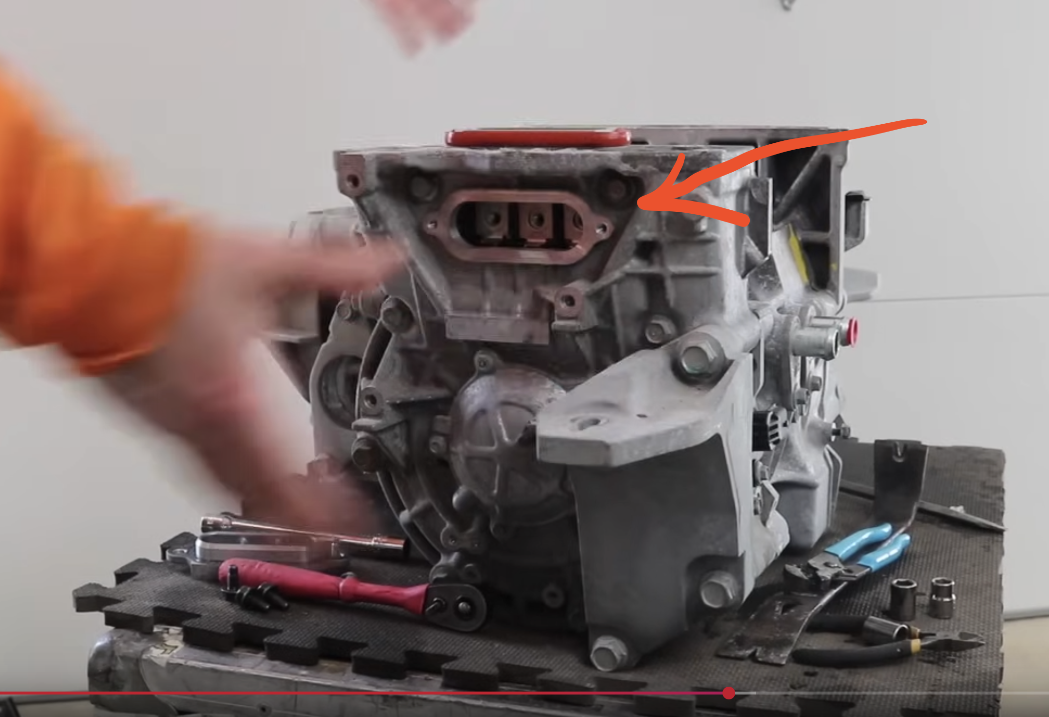
Vaguely planning...
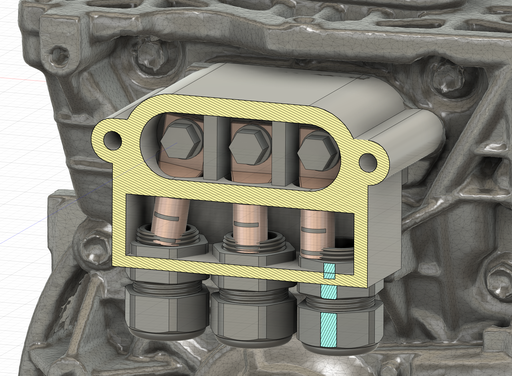
Would something like this be outrageously dangerous for the EM57 phase connectors?
I'd much want to avoid putting anything on top of the motor now (where the phases typically stick in from) as the space is tight and the whole thing is rubber mounted and therefore free to move slightly, which cooould squish the connector built on top.
But it has the side hatch for tightening the bolts.
And since I can 3D-print and lathe, I could relatively easily print out a Nylon "sleeve" for some round copper bars with holes in the middle, then use longer bolts to connect the cable lugs to the internal busbars. Sleeve for isolating the copper rods from the motor body and stabilizing them so no bending forces would be transmitted to the internal busbars.
After that it'd be just a matter of sealing of the top and printing a weatherproof case for the new connector?
As these would be only a couple of centimeters long so I'm not concerned about conductivity within the material, but the only thing that worries me slightly is that normally the inverter busbars are squeezed in there between two flat coppers, so contact surface is much more than what this would achieve seeing the round rod would only contact the busbar on one side...
Since it's HV and I lack sufficient qualification, hivemind please help am I being stupid or is this actually viable way out of my problem?
Thanks in advance!

-
Jacobsmess
- Posts: 871
- Joined: Thu Mar 02, 2023 1:30 pm
- Location: Uk
- Has thanked: 545 times
- Been thanked: 153 times
Re: [WIP] Voltswagen T2 -76
I'll let others comment on the safety, but if you do this I'd be interested in a similar setup if you're happy to sell one on? Thanks
My thoughts on the safety is it's probably fine. Provided you get good connection. The bolt will pull everything tight, so provided the faces are clean you should have the same amount of copper (or more) than originally when compared with the original busbar.
My thoughts on the safety is it's probably fine. Provided you get good connection. The bolt will pull everything tight, so provided the faces are clean you should have the same amount of copper (or more) than originally when compared with the original busbar.
-
jrbe
- Posts: 766
- Joined: Mon Jul 03, 2023 3:17 pm
- Location: CT, central shoreline, USA
- Has thanked: 360 times
- Been thanked: 249 times
Re: [WIP] Voltswagen T2 -76
You may bump into issues with your vehicle inspection if they are strict on the emi side of things by using external wires vs internal busbars. That aside, I believe this can be done safely.
This is what pops into my head
I drew the phase wire section a bit too tall, keep it short but effective to not get into vibration induced fatigue / failure where it overhangs. If you get the spacing right you could use a silicone to seal the wires to the adapter & cover. If you're really good you could do some thick orings and grooves for them and avoid the silicone mess.
And if you do nylon internally and for the cover you could print a 3rd piece / thin orange cover for the color / safety side of things.
You could also flare the standoffs on the inside to make better connection if needed / worried. Keep the gap between the busbars as your safety gap, unless they had a non-conductive wall between them. Then you need the divider to achieve the same effective air gap or a larger gap.
This is what pops into my head
And if you do nylon internally and for the cover you could print a 3rd piece / thin orange cover for the color / safety side of things.
You could also flare the standoffs on the inside to make better connection if needed / worried. Keep the gap between the busbars as your safety gap, unless they had a non-conductive wall between them. Then you need the divider to achieve the same effective air gap or a larger gap.
-
J0hannes

- Posts: 158
- Joined: Sat Nov 11, 2023 10:29 am
- Location: Finland
- Has thanked: 21 times
- Been thanked: 182 times
Re: [WIP] Voltswagen T2 -76
Simpsons did it
As this is basically a reiteration of something that exists, why not take a look how one implementation has been made and see how to adapt/improve the design from there?
https://inductiveauto.com/product/nissa ... 25VsPEtW-K
As Cera is from Finland, I don't see an issue on the emi as current rules for conversion don't really ask much regarding that if the vehicle being converted is old as this Voltswagen is.
-
Cera
- Posts: 96
- Joined: Thu Feb 10, 2022 10:08 am
- Location: Finland
- Has thanked: 49 times
- Been thanked: 71 times
Re: [WIP] Voltswagen T2 -76
Oh! Hey yes that's pretty much exactly what I had in mind!J0hannes wrote: ↑Thu Jun 26, 2025 2:41 pm Simpsons did it
As this is basically a reiteration of something that exists, why not take a look how one implementation has been made and see how to adapt/improve the design from there?
https://inductiveauto.com/product/nissa ... 25VsPEtW-K
As Cera is from Finland, I don't see an issue on the emi as current rules for conversion don't really ask much regarding that if the vehicle being converted is old as this Voltswagen is.
Yeah I don't think EMI restrictions/rules apply to 1976 here, so should be all good inspection-wise.
Yes adding spacers like this between the wires sounds good. I might just steal the idea of using those threaded cable passthroughs used in the linked product for waterproof connections.jrbe wrote: ↑Thu Jun 26, 2025 11:56 am This is what pops into my head I drew the phase wire section a bit too tall, keep it short but effective to not get into vibration induced fatigue / failure where it overhangs. If you get the spacing right you could use a silicone to seal the wires to the adapter & cover.
Of course! I'll see what I can doJacobsmess wrote: ↑Thu Jun 26, 2025 11:27 am I'll let others comment on the safety, but if you do this I'd be interested in a similar setup if you're happy to sell one on? Thanks
-
ianlighting

- Posts: 275
- Joined: Tue Apr 02, 2024 10:01 am
- Location: Uk
- Has thanked: 258 times
- Been thanked: 189 times
Re: [WIP] Voltswagen T2 -76
Did you see what @Windraver did for this on DIY Electric Car? 3D printed covers used to connect on top. I know you said you wanted to avoid that, but might be food for thought and he shared his files.
https://www.diyelectriccar.com/threads/ ... st-1126800
https://www.diyelectriccar.com/threads/ ... st-1126800
-
Cera
- Posts: 96
- Joined: Thu Feb 10, 2022 10:08 am
- Location: Finland
- Has thanked: 49 times
- Been thanked: 71 times
Re: [WIP] Voltswagen T2 -76
Yes I saw thatianlighting wrote: ↑Fri Jun 27, 2025 5:04 am Did you see what @Windraver did for this on DIY Electric Car? 3D printed covers used to connect on top. I know you said you wanted to avoid that, but might be food for thought and he shared his files.
https://www.diyelectriccar.com/threads/ ... st-1126800
-
Cera
- Posts: 96
- Joined: Thu Feb 10, 2022 10:08 am
- Location: Finland
- Has thanked: 49 times
- Been thanked: 71 times
Re: [WIP] Voltswagen T2 -76
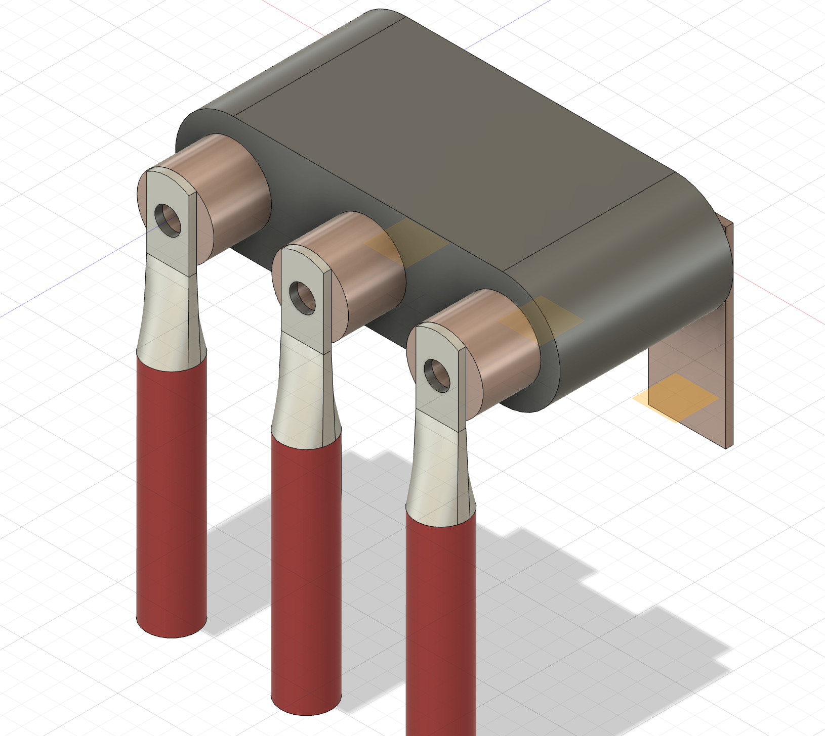
Yeah I think this should be doable.
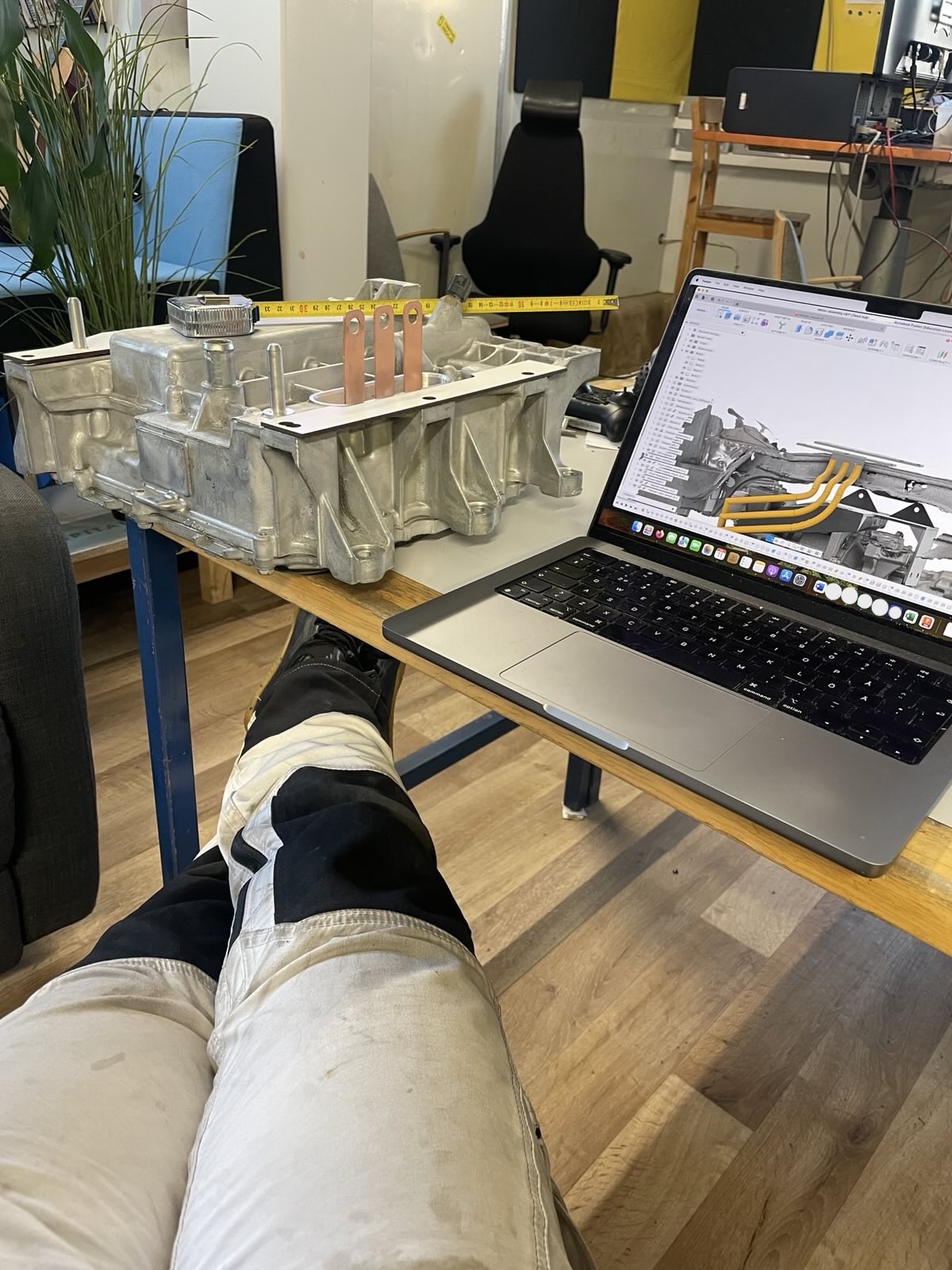
There's a protrusion from the motor case just below the rearmost phase in my setup, which necessitates longer copper and bolts, currently around 80mm length. Could shave off some 1.5cm from that if I could bypass that screw protrusion somehow. Oh well.
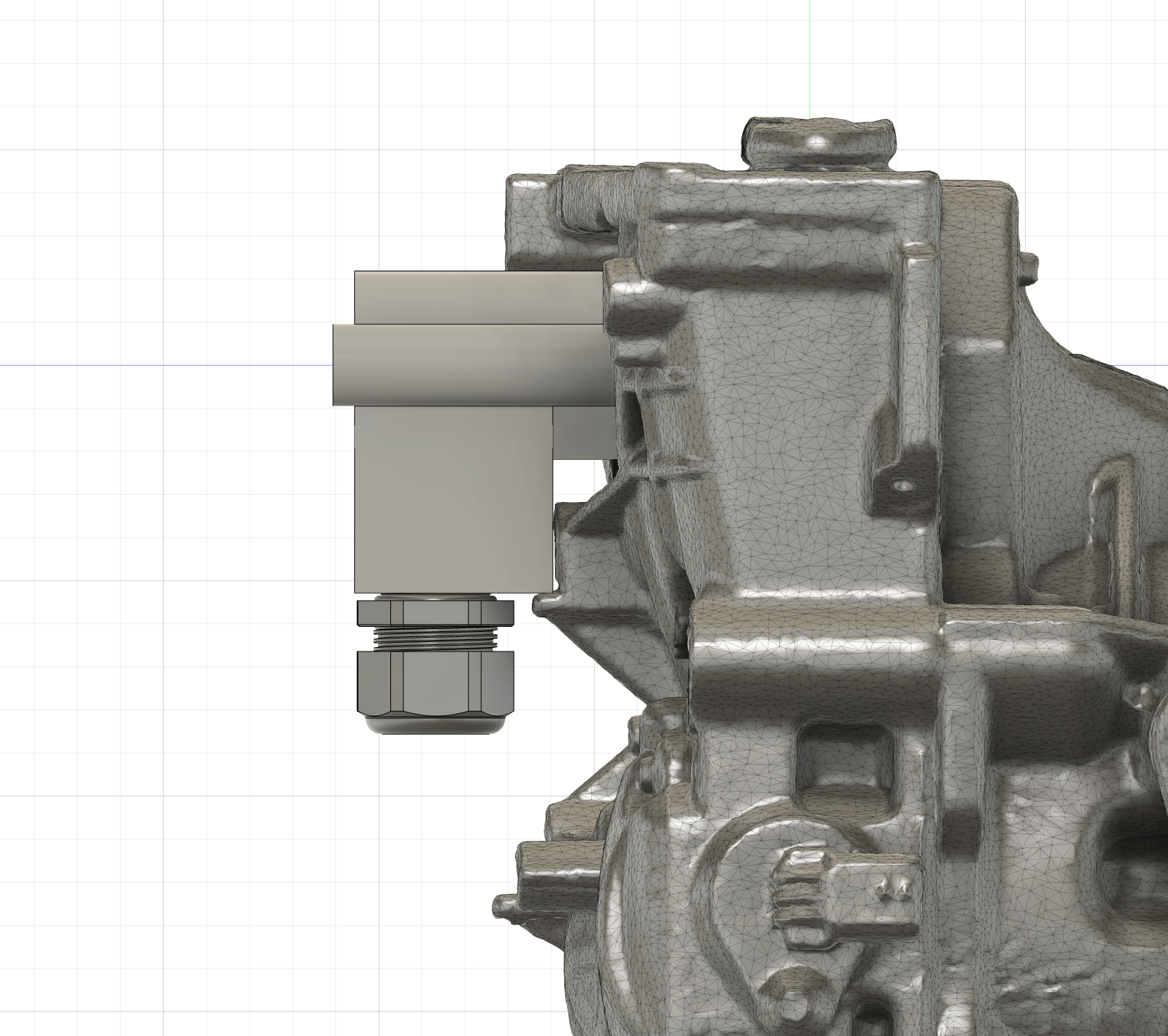
But anyway with this my phases would end up looking something like this:
(I'm learning how to use Sweep -tool in Fusion )
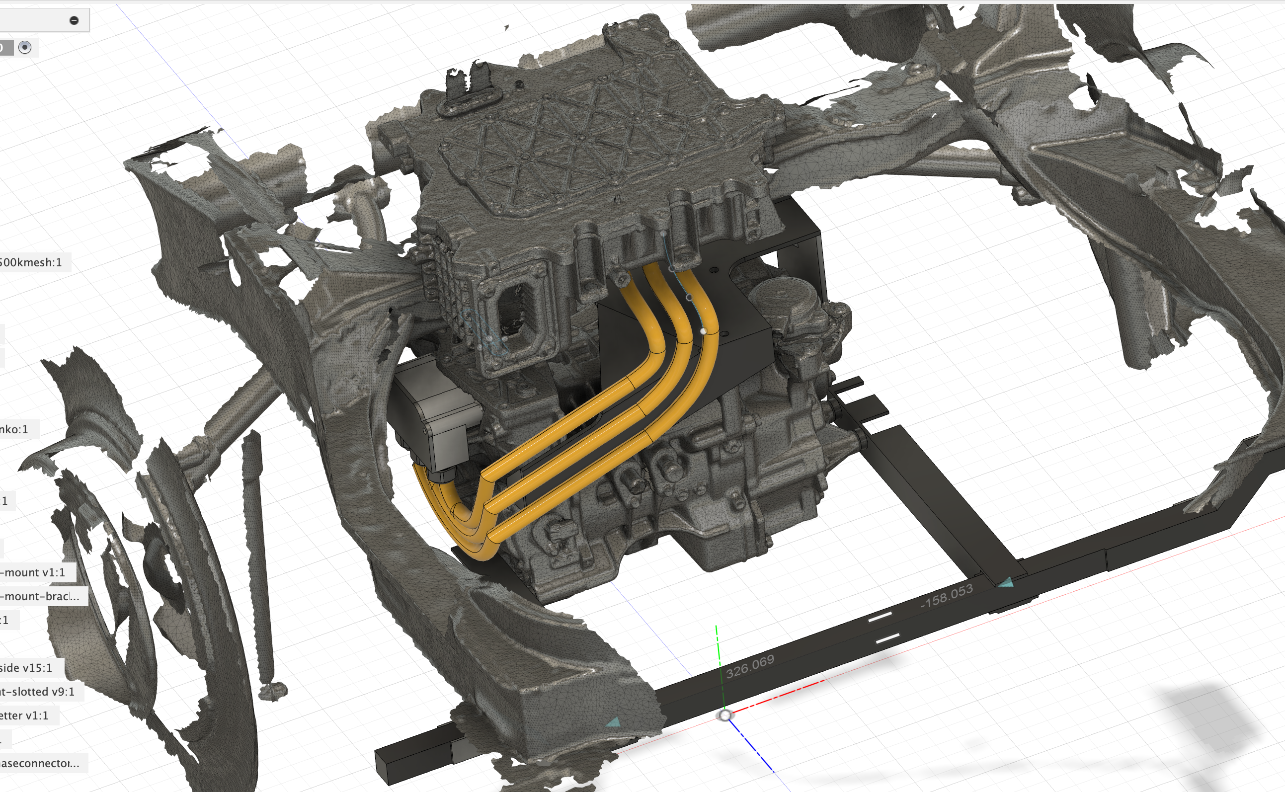
I can also attach the wiring to the motor mount I made previously, as I understand EU directive requires bolting down HV wiring every 20cm or so.
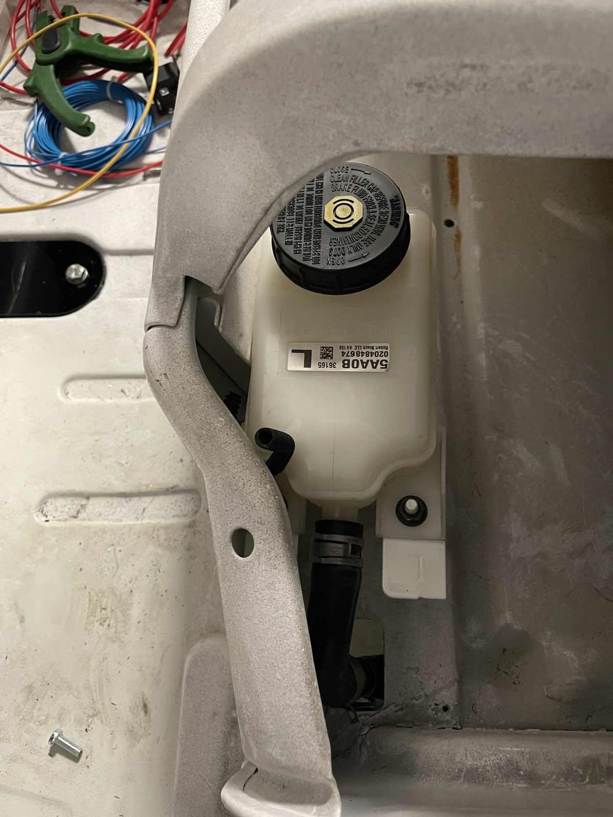
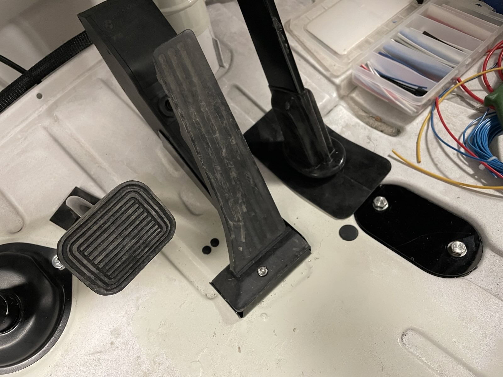
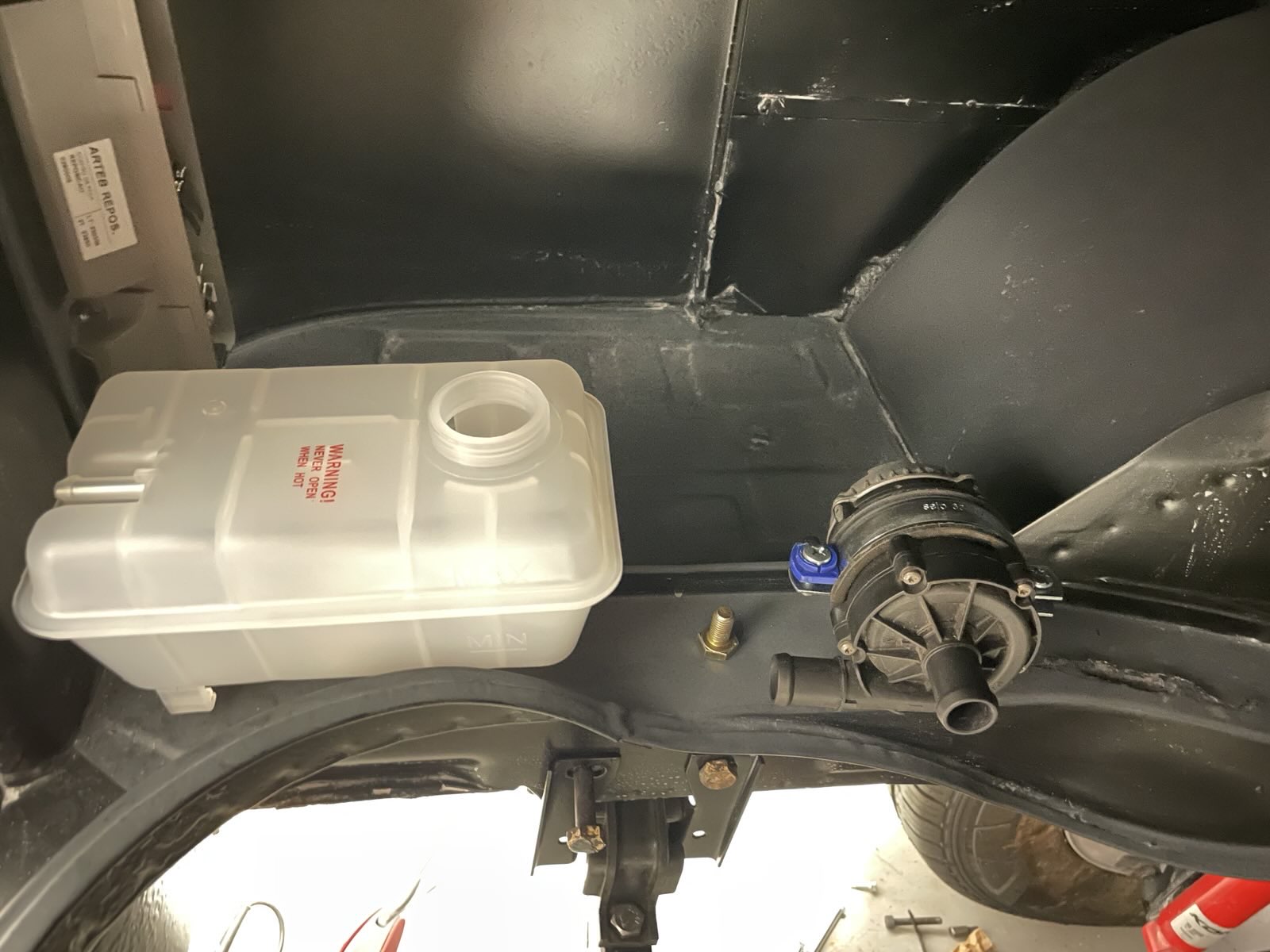
In other news, brake fluid reservoir finally mounted. This one's from Nissan Murano and had built-in sensor for fluid level warning light. I have the iBooster below and the actual reservoir here in the cabin, so my main worry (more than actual CuNi brake lines) is that the hose between those detaches or starts leaking. This way I'll have a warning light turning on way before the master cylinder actually runs out of fluid, so plenty of time for a safe stop.
Gas pedal also fully mounted finally and while at that, started plugging the (now) unnecessary holes in the cabin floor with rubber grommets and lasercut plates too.
There's a protrusion from the motor case just below the rearmost phase in my setup, which necessitates longer copper and bolts, currently around 80mm length. Could shave off some 1.5cm from that if I could bypass that screw protrusion somehow. Oh well.
But anyway with this my phases would end up looking something like this:
(I'm learning how to use Sweep -tool in Fusion
I can also attach the wiring to the motor mount I made previously, as I understand EU directive requires bolting down HV wiring every 20cm or so.
In other news, brake fluid reservoir finally mounted. This one's from Nissan Murano and had built-in sensor for fluid level warning light. I have the iBooster below and the actual reservoir here in the cabin, so my main worry (more than actual CuNi brake lines) is that the hose between those detaches or starts leaking. This way I'll have a warning light turning on way before the master cylinder actually runs out of fluid, so plenty of time for a safe stop.
Gas pedal also fully mounted finally
-
Cera
- Posts: 96
- Joined: Thu Feb 10, 2022 10:08 am
- Location: Finland
- Has thanked: 49 times
- Been thanked: 71 times
Re: [WIP] Voltswagen T2 -76
SO. MUCH. WIRING.
Making the main harness.
12V battery, etc are located in the rear. Main fusebox is in the front below dash. I'm upgrading the original 1970's wiring diagram slightly.
- Adding main fuses (Midi 50A) to battery positive so no wire goes unfused. Original schematic has no protection for shorts in the main harness before the dash fusebox.
- Original wiring uses 1*6mm2 from battery to front and 1*6mm2 from front ignition back to rear for starter/cranking. I'll be keeping 2*6mm2 but using both for feeding power to the front. Double the capacity, less voltage drop.
- Instead of feeding all the main fusebox current through ignition lock, I got a cheap-ish AEV14012 to use as a main contactor, controlled by the ignition lock. Slightly overkill for 12V but hey, you use what you find.
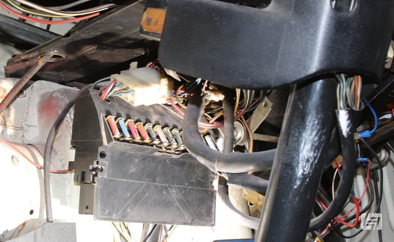
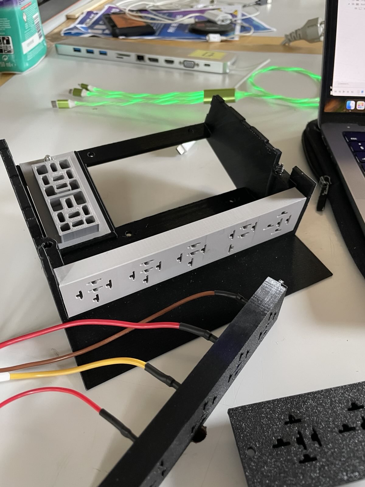
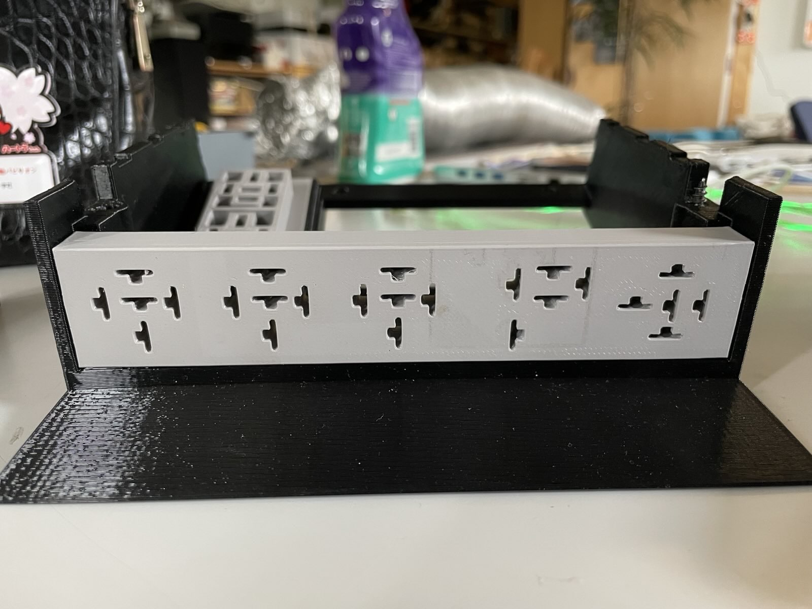
- Upgrading from the old fusebox (10 * continental style):
To a modern one (20 * blade fuses):
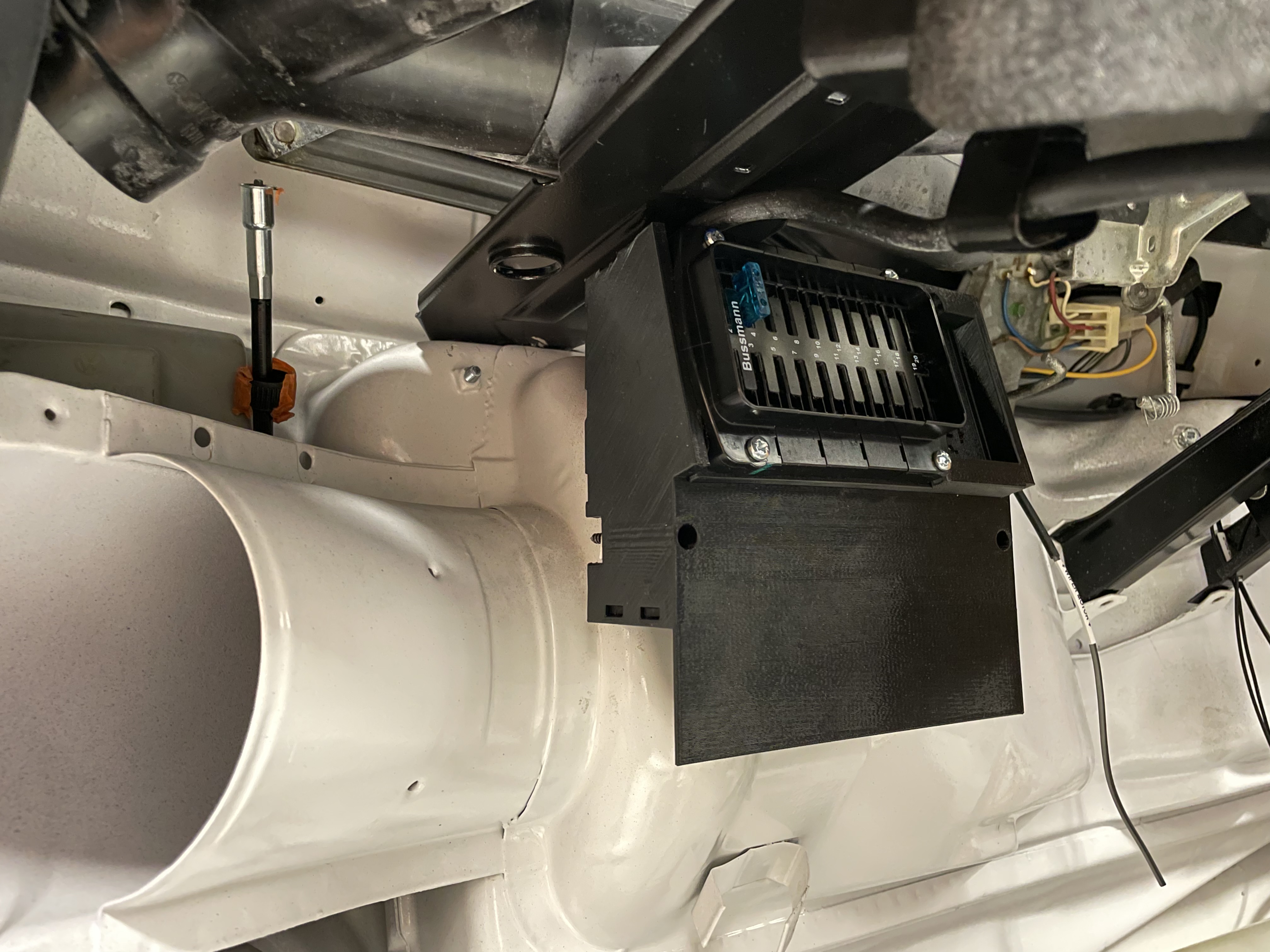
I took the old fusebox for a base and modeled a frame for Bussmann 15712, kept the relay sockets where they were and was able to add two extra standard sockets next to the fuses, since the blade fuse box takes less width.
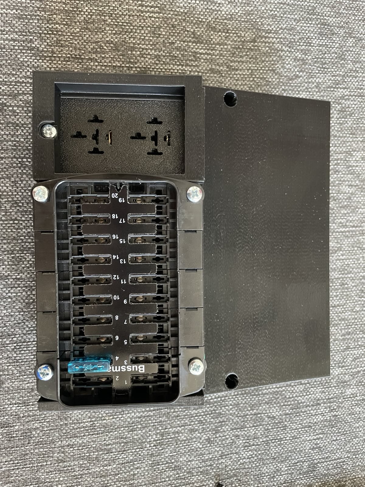
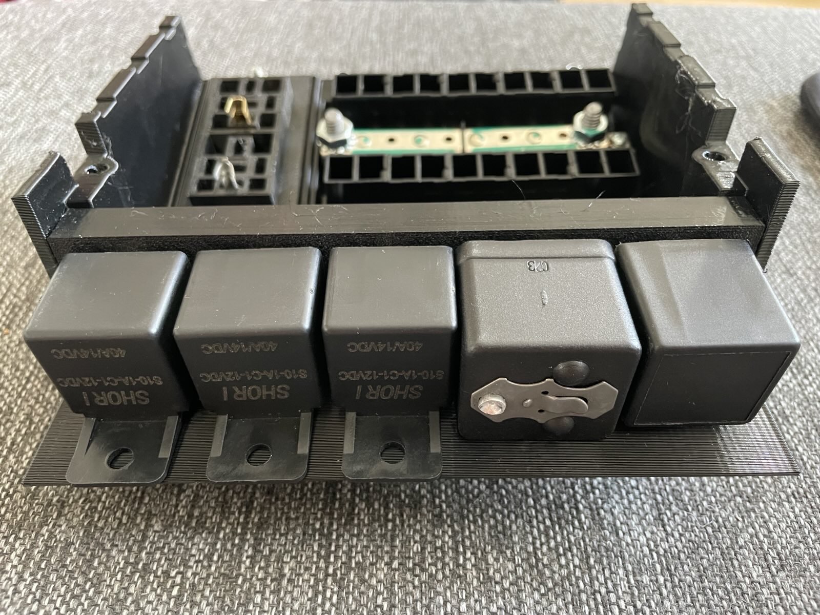
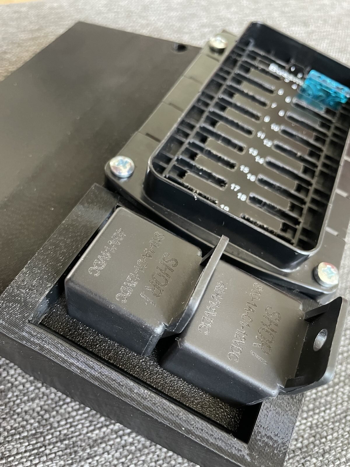
... Then being slightly paranoid about PETG heat resistance, I went on to re-print the relay sockets from polycarbonate. Just in case.
I'll be splitting the busbar in the fusebox into two rails:
Rail 1: Constantly hot (hazard lights, interior lights, etc)
Rail 2: Switched power (from main 12V contactor; pretty much everything else)
Might go on to make a "Camp mode" rail in the future too. splitting off a small segment from the switched rail, then running power to it via a relay controlled by either Rail 1 via a button in the dashboard or Rail 2 (through a diode).
That way I could choose to power on radio, fridge, mby something else in the future without having to have the key in the ignition... And with a possibility of adding low voltage guard and less risk of draining the 12V battery overnight. We'll see!
----
Doing the wiring, I'm trying avoid splices in the wires as much as I can.
I haven't yet discovered how to de-pin the connectors iBooster uses. I have the pigtails but would prefer to run straight wires to plug.
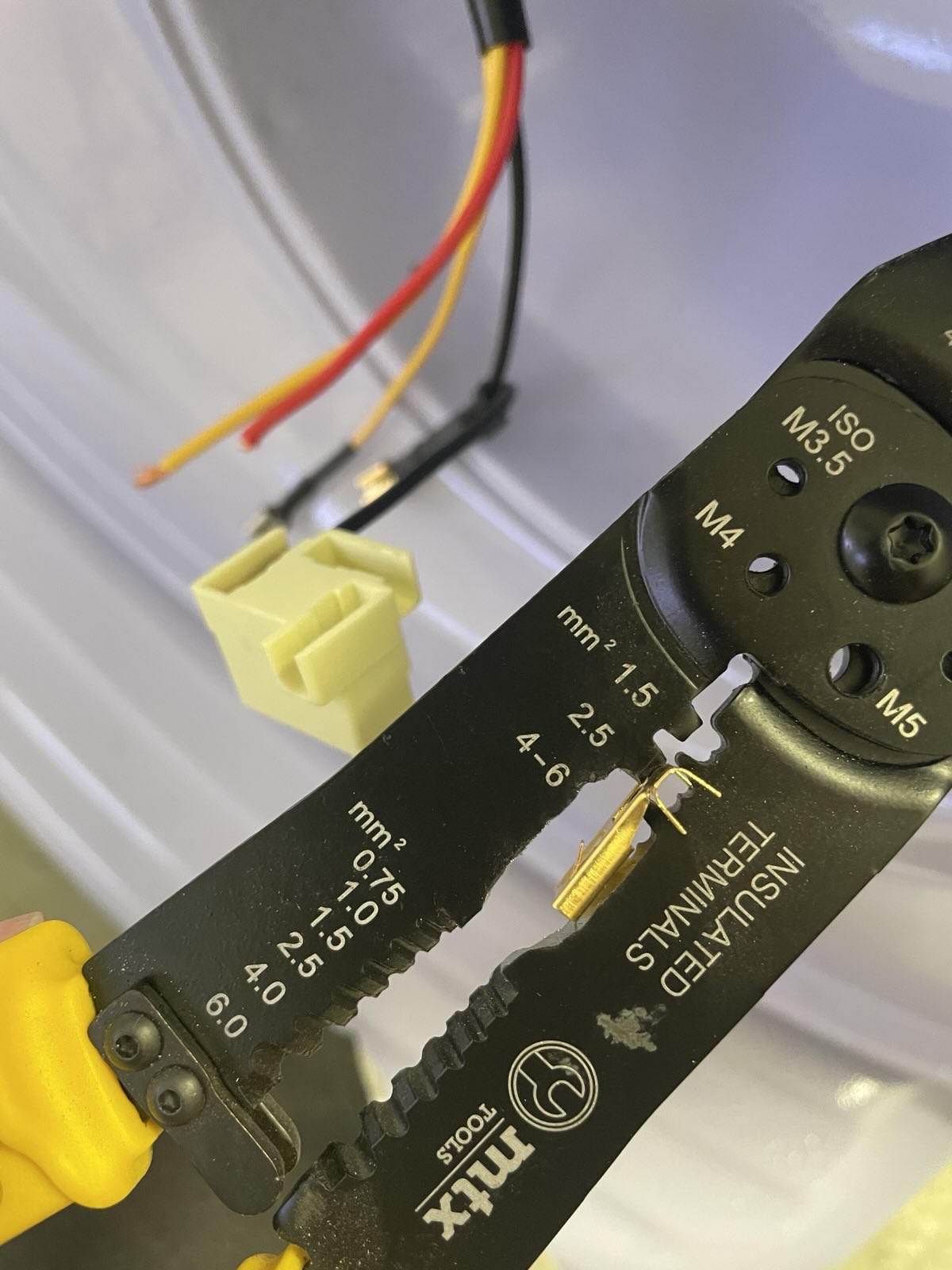
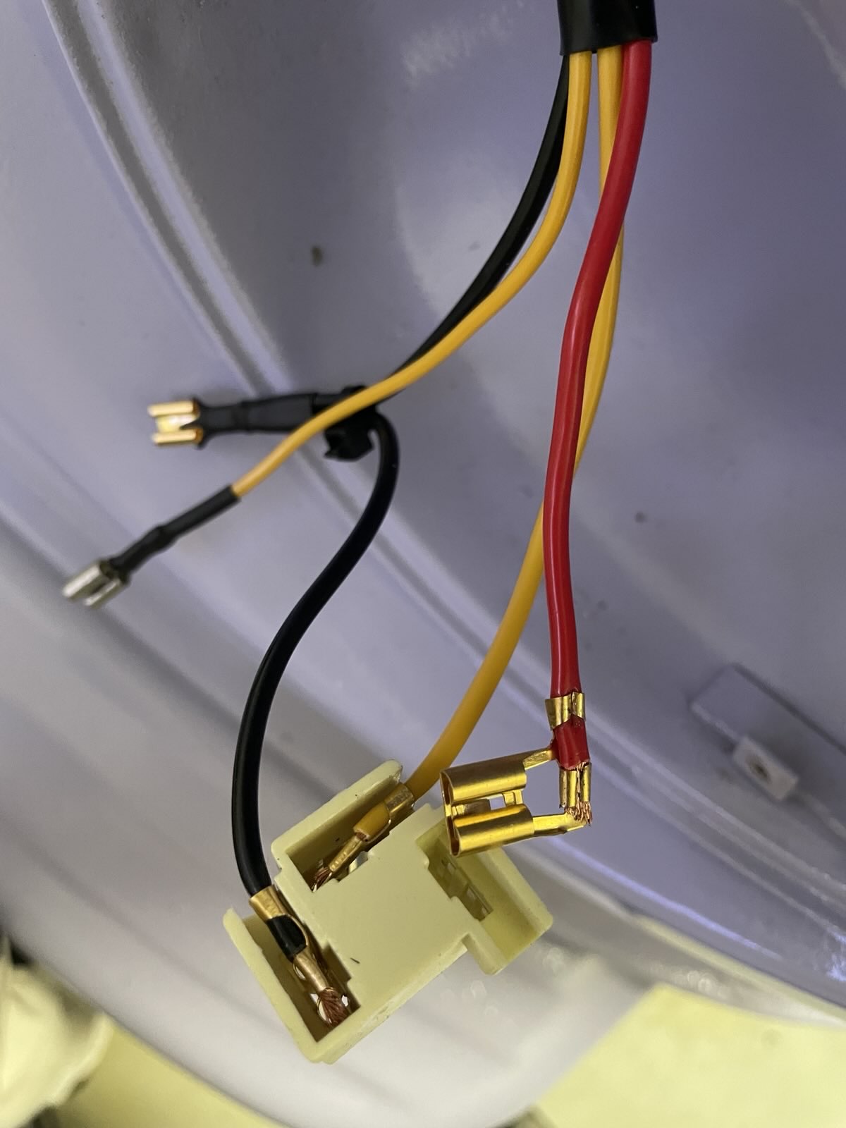
H4 connectors turned out to be quirky for this as well. The ones I bought came with pigtails and use these flag -style connectors. Had to buy a cheap pair of crimpers and modify them a bit for being able to crimp these.
---
Taking a break from wiring and installing the inverter.
Designing a mounting bracket.
Plasma!
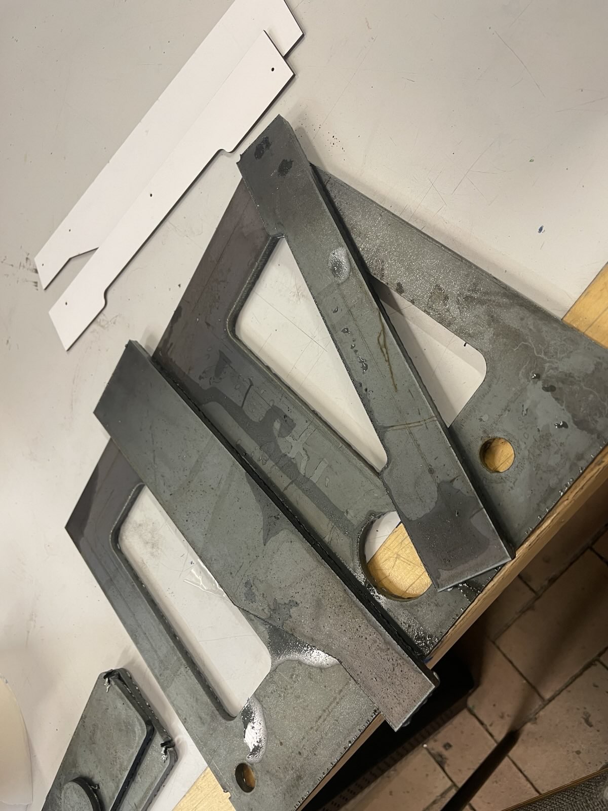
Welding
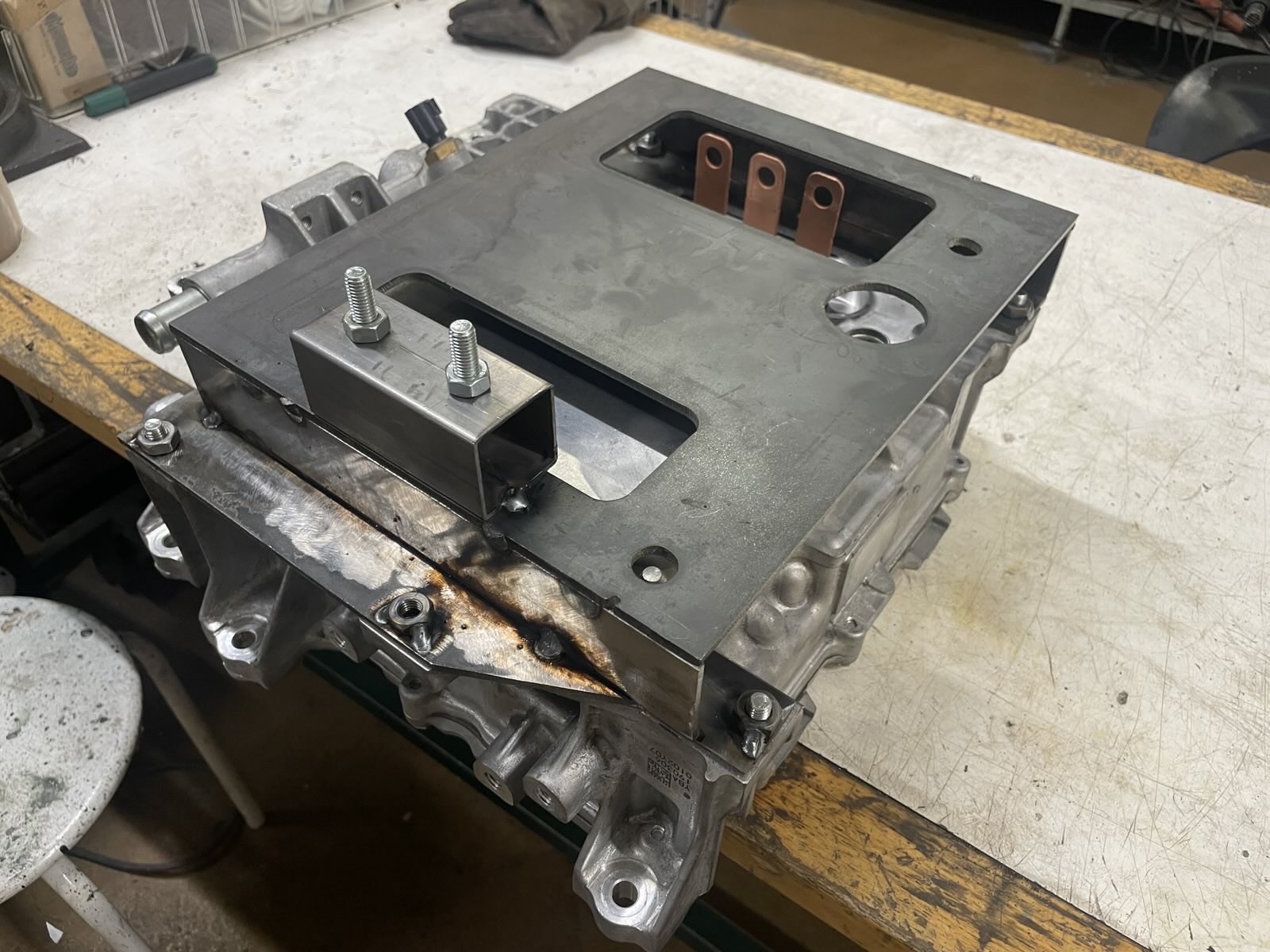
Inverter lives there now.
---
Upcoming challenges to solve:
Need to find a radiator and fans for the coolant system. Maybe a smaller reservoir too. Probably will be installing them to the left side of the motor bay, there's plenty room.
Need to decide on where to install Zombie. Since the harness travels the whole length of the vehicle and through multiple passthroughs, it'll be annoying to add wires later.
Main fusebox is in the front as are ignition, throttle and gear selector. Currently kind of leaning towards installing it somewhere below the dash.
But then I need to figure out how many wires I need to run to the rear. HV contactors, coolant pump, IVT shunt CAN, something else..? etc...
Gah!
Anyway, happy with the progress currently.
Making the main harness.
12V battery, etc are located in the rear. Main fusebox is in the front below dash. I'm upgrading the original 1970's wiring diagram slightly.
- Adding main fuses (Midi 50A) to battery positive so no wire goes unfused. Original schematic has no protection for shorts in the main harness before the dash fusebox.
- Original wiring uses 1*6mm2 from battery to front and 1*6mm2 from front ignition back to rear for starter/cranking. I'll be keeping 2*6mm2 but using both for feeding power to the front. Double the capacity, less voltage drop.
- Instead of feeding all the main fusebox current through ignition lock, I got a cheap-ish AEV14012 to use as a main contactor, controlled by the ignition lock. Slightly overkill for 12V but hey, you use what you find.
- Upgrading from the old fusebox (10 * continental style):
To a modern one (20 * blade fuses):
I took the old fusebox for a base and modeled a frame for Bussmann 15712, kept the relay sockets where they were and was able to add two extra standard sockets next to the fuses, since the blade fuse box takes less width.
... Then being slightly paranoid about PETG heat resistance, I went on to re-print the relay sockets from polycarbonate.
Just in case.I'll be splitting the busbar in the fusebox into two rails:
Rail 1: Constantly hot (hazard lights, interior lights, etc)
Rail 2: Switched power (from main 12V contactor; pretty much everything else)
Might go on to make a "Camp mode" rail in the future too.
 splitting off a small segment from the switched rail, then running power to it via a relay controlled by either Rail 1 via a button in the dashboard or Rail 2 (through a diode).
That way I could choose to power on radio, fridge, mby something else in the future without having to have the key in the ignition... And with a possibility of adding low voltage guard and less risk of draining the 12V battery overnight. We'll see!
----
Doing the wiring, I'm trying avoid splices in the wires as much as I can.
I haven't yet discovered how to de-pin the connectors iBooster uses. I have the pigtails but would prefer to run straight wires to plug.
H4 connectors turned out to be quirky for this as well. The ones I bought came with pigtails and use these flag -style connectors. Had to buy a cheap pair of crimpers and modify them a bit for being able to crimp these.
---
Taking a break from wiring and installing the inverter.
Designing a mounting bracket.
Plasma!
Welding
Inverter lives there now.
---
Upcoming challenges to solve:
Need to find a radiator and fans for the coolant system. Maybe a smaller reservoir too. Probably will be installing them to the left side of the motor bay, there's plenty room.
Need to decide on where to install Zombie. Since the harness travels the whole length of the vehicle and through multiple passthroughs, it'll be annoying to add wires later.
Main fusebox is in the front as are ignition, throttle and gear selector. Currently kind of leaning towards installing it somewhere below the dash.
But then I need to figure out how many wires I need to run to the rear. HV contactors, coolant pump, IVT shunt CAN, something else..? etc...
Gah!
Anyway, happy with the progress currently.
-
ianlighting
- Posts: 275
- Joined: Tue Apr 02, 2024 10:01 am
- Location: Uk
- Has thanked: 258 times
- Been thanked: 189 times
Re: [WIP] Voltswagen T2 -76
The quality of your updates is always so impressive compared to mine!
Camp mode - yes, I agree. I’m going to be doing the same at some point, maybe after the summer season is over so I don’t mess up what works.
In my case, turning on means the annoying brake vac pump comes on intermittently, which I know you don’t have. But my coolant pump looks very similar to yours and there’s a constant whine from it, so I need to be able to turn on power to stuff (I’m thinking about induction hob at some point) without that doing its thing.
I have found with silent running a risk of walking away and forgetting it’s still switched on. More than once I’ve started wandering off and only realised I’d left it on when I heard the brrrrr of the vac pump starting up!
-
Cera
- Posts: 96
- Joined: Thu Feb 10, 2022 10:08 am
- Location: Finland
- Has thanked: 49 times
- Been thanked: 71 times
Re: [WIP] Voltswagen T2 -76
Hmm. Might also be getting 2nd (102nd, at least) thoughts about the battery pack.
The more I look the harder it seems to mount the M3 modules safely darn mechanical levitation!
That added to the imbalance issues some people have been having, BMS support, etc.
Currently as far as I understand it, the original BMS might or might not work with some Batman trickery? I should take yet another look at Damien's videos about these and the PCS.
Orion 2 BMS on the other hand requires soldering all the tiny wires to the slave boards, which looks like a thing I'm unsure if I want to tackle anytime soon.
I might be able to sell the pack locally, then find something "easier to work with" instead. But trying to avoid hasty calls on this. I know some people like brat are running M3 pack so it should be doable. Maybe just a lil bit too difficult for my level and first build.
Just pondering.
The more I look the harder it seems to mount the M3 modules safely
 darn mechanical levitation!
That added to the imbalance issues some people have been having, BMS support, etc.
Currently as far as I understand it, the original BMS might or might not work with some Batman trickery? I should take yet another look at Damien's videos about these and the PCS.
Orion 2 BMS on the other hand requires soldering all the tiny wires to the slave boards, which looks like a thing I'm unsure if I want to tackle anytime soon.
I might be able to sell the pack locally, then find something "easier to work with" instead. But trying to avoid hasty calls on this. I know some people like brat are running M3 pack so it should be doable. Maybe just a lil bit too difficult for my level and first build.
Just pondering.
-
ianlighting
- Posts: 275
- Joined: Tue Apr 02, 2024 10:01 am
- Location: Uk
- Has thanked: 258 times
- Been thanked: 189 times
Re: [WIP] Voltswagen T2 -76
I forget if you were planning to mount under the rear bench seat or under the bus somewhere. You should have the original VW mounting holes for minibus seats in the floor and the seat belt mounts on the angled walled behind that. That’s what I used as the basis for a frame for my box. Can’t remember what level of detail about this I shared in my build thread, but I can dig out photos if it’s useful.
-
Cera
- Posts: 96
- Joined: Thu Feb 10, 2022 10:08 am
- Location: Finland
- Has thanked: 49 times
- Been thanked: 71 times
Re: [WIP] Voltswagen T2 -76
Yeah I have the bench seat mounting brackets and am confident I can find multiple ways of attaching any battery box to the van itself.ianlighting wrote: ↑Sun Aug 03, 2025 7:12 am I forget if you were planning to mount under the rear bench seat or under the bus somewhere. You should have the original VW mounting holes for minibus seats in the floor and the seat belt mounts on the angled walled behind that. That’s what I used as the basis for a frame for my box. Can’t remember what level of detail about this I shared in my build thread, but I can dig out photos if it’s useful.
... But making a battery box for the M3 modules is still pain due to their fragile construction
I've considered multiple approaches from the welded L-bracket frame (which I'm not entirely happy with) to @nkiarnan's plastic inserts inside a steel box (but CNC milling plastic inserts seems to cost a lot). Bottom line seems to be their mounting (inside any box) ends up being more costly and difficult than any of the smaller rectangular modules which can just be laid next to each others like bricks.
Then on top of that, even if I'd go ahead and pull the trigger on the POM-C inserts or something similar, I'm still uncertain about my skills in actually making them work. I've seen some people using them so my impression is that they have to, and *do* work if you know what you're doing, but I'm not entirely sure how people have done that and if it's something I'm comfortable attempting myself since I'm already struggling this much with the "easiest" part (mechanical mounting).
I still don't fully understand what the M3 BMS requires to get it working (and if it's possible to get it working why people choose Orion 2 over it).
But lots of this is me not understanding the battery tech and related components well enough yet. We need some "BMS for dummies" options, pro's/con's and compatibility chart to wiki.
Basically current thinking is; 6000e for the battery modules + 1500-2000e for Orion BMS (and worst case screwing something up when wiring and blowing a module) + 500-1000e for enclosure it's just perhaps not worth it for me. I don't know yet.
Bit of a desperation and frustration mixed in I admit since I've been at this for many years and it'd be nice to finally get moving and batteries seem to be the last big hurdle now.
-
johu
- Site Admin
- Posts: 7182
- Joined: Thu Nov 08, 2018 10:52 pm
- Location: Kassel/Germany
- Has thanked: 552 times
- Been thanked: 1913 times
- Contact:
Re: [WIP] Voltswagen T2 -76
Maybe I can talk you into giving the open source option a try https://openinverter.org/wiki/16-cell_BMS
I think Tom or Damien should be able to comment on the state of the M3 BMS hacking
I think Tom or Damien should be able to comment on the state of the M3 BMS hacking
Support R/D and forum on Patreon: https://patreon.com/openinverter - Subscribe on odysee: https://odysee.com/@openinverter:9
-
tom91
- Posts: 2962
- Joined: Fri Mar 01, 2019 9:15 pm
- Location: Bicester, Oxfordshire
- Has thanked: 328 times
- Been thanked: 847 times
Re: [WIP] Voltswagen T2 -76
The Damien M3 BMS status is aligned roughly with his latest video on it.
Again very little feedback from the community so this end-up in the freezer again. I have heard of an issue with 23s and 25s modules that I believe I have solved now. But no real feedback beyond that.
Again very little feedback from the community so this end-up in the freezer again. I have heard of an issue with 23s and 25s modules that I believe I have solved now. But no real feedback beyond that.
-
Cera
- Posts: 96
- Joined: Thu Feb 10, 2022 10:08 am
- Location: Finland
- Has thanked: 49 times
- Been thanked: 71 times
Re: [WIP] Voltswagen T2 -76
Heh yeah, we'll see. I'm watching "Understanding basics of canbus" and similar one after another currently, it's a long way 'till I'm up to providing useful feedback I'm afraid but who knows, maybe someday.
and don't get me wrong when I said I was hopeful there'd be more users at this point for these, I'm very, very grateful for Damien and the whole community for all the work done!
but who knows, maybe someday. and don't get me wrong when I said I was hopeful there'd be more users at this point for these, I'm very, very grateful for Damien and the whole community for all the work done!
-
muehlpower

- Posts: 807
- Joined: Fri Oct 11, 2019 10:51 am
- Location: Germany Fürstenfeldbruck
- Has thanked: 18 times
- Been thanked: 186 times
Re: [WIP] Voltswagen T2 -76
I am following the development of the M3 BMS with great interest. I have solved the housing problem and have therefore decided on M3 modules. Until something better comes along, I am using the original M3 HV controller and the CAN messages it outputs. This gives me a good overview of the individual cell voltages and temperatures. I don't know if and when it will balance. The housing accommodates a full LR package, two side by side and two on top of each other. The modules are attached to the existing holes and with various clamp holders, all made of aluminum profiles. The lines and the distribution of the cooling water are housed in the rectangular tube in the middle.
- Attachments
-
-
-
Cera
- Posts: 96
- Joined: Thu Feb 10, 2022 10:08 am
- Location: Finland
- Has thanked: 49 times
- Been thanked: 71 times
Re: [WIP] Voltswagen T2 -76
Doing Zombie wiring next. Looking for hivemind again.
Basically I'm doing most of the 12V wiring as per original; using the existing wiring channel under the floor for running power feeds from the rear motor room to the front fusebox throughout the whole length of the vehicle. 12V battery lives in the rear next to the motor, HVJB, all the usual "under the bonnet" stuff.
This wiring channel currently contains:
2 * 6,0mm2 main power feed from battery main fuses to front fusebox
3 * 1,5mm2 from dash light switch to tail lights, turn indicators
But I'm having difficulties deciding which option is better for Zombie or does this even matter.
1) If I install Zombie in the front cabin (somewhere below the dashboard), it'll be easy to wire up throttle, gear select, basically all the control hardware. But I'll end up having to run contactor wiring, Leaf CAN wiring, etc. with long wires all the way to the rear next to the power feeds. (EMI concern?)
2) If I install Zombie in the rear motor bay, it'll be easy to install HV contactor controls, CAN, etc. but I'll end up having to run long wires from throttle, ignition, start, etc from front to rear.
In any case the amount of wires will be roughly the same as far as my current schematics go and I can't seem to decide which is better. On the other hand long throttle signal wiring next to the main 12V feeds sounds annoying, on the other, long HV contactor wiring and CAN does too.
Am I overthinking this? Is EMI even a concern with these? Am I just missing something incredibly obvious which favors one option over the other?