I'm able to load Damien's FW and use the serial interface (menu, debug messages) via a USB UART bridge on CONN8, but I still don't have USB serial. I thought there might be a clock issue (saw that happen with a USB audio device at work recently) and the load caps on Y2 looked too large, but changing those to 10pF didn't help. I haven't looked at the clock with the nice scope, but it looked like it was right on 8Mhz with my scope meter. The 32KHz crystal doesn't look like it's being used because It's not in a low-power mode.
Really scratching my head on this.
Tesla Charger Support Thread
-
johu

- Site Admin
- Posts: 7182
- Joined: Thu Nov 08, 2018 10:52 pm
- Location: Kassel/Germany
- Has thanked: 552 times
- Been thanked: 1913 times
- Contact:
Re: Tesla Charger Support Thread
The STM32 doesn't handle any USB, it's the FTDI chip. Maybe some dodgy connection in that proximity.
You can try my alternative firmware because that doesn't use USB anyway
https://openinverter.org/wiki/GEN2
You can try my alternative firmware because that doesn't use USB anyway
https://openinverter.org/wiki/GEN2
Support R/D and forum on Patreon: https://patreon.com/openinverter - Subscribe on odysee: https://odysee.com/@openinverter:9
-
johu
- Site Admin
- Posts: 7182
- Joined: Thu Nov 08, 2018 10:52 pm
- Location: Kassel/Germany
- Has thanked: 552 times
- Been thanked: 1913 times
- Contact:
Re: Tesla Charger Support Thread
Oh sorry, I thought all V5 boards were that architecture.
Support R/D and forum on Patreon: https://patreon.com/openinverter - Subscribe on odysee: https://odysee.com/@openinverter:9
Re: Tesla Charger Support Thread
I've got your firmware on now and the wifi interface is working, so I think that will do what I need. I hate to leave it with features not working though. Makes me think I could have other problems.
-
johu
- Site Admin
- Posts: 7182
- Joined: Thu Nov 08, 2018 10:52 pm
- Location: Kassel/Germany
- Has thanked: 552 times
- Been thanked: 1913 times
- Contact:
Re: Tesla Charger Support Thread
Oh wow, I wasn't even aware Damien attempted to do USB directly with the STM32. Maybe he succeeded as much as I did and thats what you're seeing. Damien?
Support R/D and forum on Patreon: https://patreon.com/openinverter - Subscribe on odysee: https://odysee.com/@openinverter:9
-
Jack Bauer

- Posts: 4000
- Joined: Wed Dec 12, 2018 5:24 pm
- Location: Ireland
- Has thanked: 153 times
- Been thanked: 1115 times
- Contact:
Re: Tesla Charger Support Thread
No I never did direct usb. On the 103 usb and can share them same interrrupt so both can't work at the same time. There is an ftdi232 chip bridging usb to serial 1.
I'm going to need a hacksaw
Re: Tesla Charger Support Thread
I see. So on V5 (Not V5a) USB lines were brought in the the STM32 and just not used? If so that's good enough for me.
-
Jack Bauer
- Posts: 4000
- Joined: Wed Dec 12, 2018 5:24 pm
- Location: Ireland
- Has thanked: 153 times
- Been thanked: 1115 times
- Contact:
-
Jack Bauer
- Posts: 4000
- Joined: Wed Dec 12, 2018 5:24 pm
- Location: Ireland
- Has thanked: 153 times
- Been thanked: 1115 times
- Contact:
Re: Tesla Charger Support Thread
New V3 STM32 based design for Gen 3 charger released which support the new Openinverter firmware with wifi interface :
viewtopic.php?f=10&t=1323
Sources on Github :https://github.com/damienmaguire/Tesla-Gen3-Charger
Kits now reduced by 100 euros on webshop :
https://www.evbmw.com/index.php/evbmw-w ... sla-boards
viewtopic.php?f=10&t=1323
Sources on Github :https://github.com/damienmaguire/Tesla-Gen3-Charger
Kits now reduced by 100 euros on webshop :
https://www.evbmw.com/index.php/evbmw-w ... sla-boards
- Attachments
-
I'm going to need a hacksaw
-
TheLifeHacker
- Posts: 4
- Joined: Thu Mar 28, 2019 3:55 am
- Location: Los Angeles USA
Re: Tesla Charger Support Thread
Problem solved by reading more threads on the forum. 
Can only charge one module at a time:
SET-UP:
Gen 2 CHARGER
V4 PCB
120V USA
When attempting to charge all three modules the entire charger fails. Any recommendations?
Can only charge one module at a time:
SET-UP:
Gen 2 CHARGER
V4 PCB
120V USA
When attempting to charge all three modules the entire charger fails. Any recommendations?
-
Johaljaswant
- Posts: 56
- Joined: Wed Jul 03, 2019 1:35 pm
- Location: USA
Re: Tesla Charger Support Thread
USA single phase 240 volt supply.
V5 board , I did try two Tesla charger 1014963-00-C and 1014963-00-K.
On both cases EVSE kick in but dc voltage showing 0, Not charging,attached screenshot.
V5 board , I did try two Tesla charger 1014963-00-C and 1014963-00-K.
On both cases EVSE kick in but dc voltage showing 0, Not charging,attached screenshot.
-
Jack Bauer
- Posts: 4000
- Joined: Wed Dec 12, 2018 5:24 pm
- Location: Ireland
- Has thanked: 153 times
- Been thanked: 1115 times
- Contact:
Re: Tesla Charger Support Thread
Just to reiterate can folks with V5 (or later) boards please update to the new firmware :
https://openinverter.org/shop/index.php ... duct_id=67
https://openinverter.org/wiki/GEN2
https://openinverter.org/shop/index.php ... duct_id=67
https://openinverter.org/wiki/GEN2
I'm going to need a hacksaw
-
Jack Bauer
- Posts: 4000
- Joined: Wed Dec 12, 2018 5:24 pm
- Location: Ireland
- Has thanked: 153 times
- Been thanked: 1115 times
- Contact:
Re: Tesla Charger Support Thread
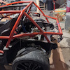
New gen 3 controller prototypes ready for testing:)
- Attachments
-
I'm going to need a hacksaw
-
JustARegularNoob
- Posts: 2
- Joined: Sun Jan 24, 2021 12:17 am
Re: Tesla Charger Support Thread
Hi,
Watched the gen 3 charger wiring video and am just a little confused at a couple of things:
Here's my understanding - Ground, 12V, Activate and Enable are connected for each charging module, and rightfully so there are 3 dedicated pins for each activate and enable, enabling the 3 charging modules to each have activate and enable. However there's only 2 pins in total for Ground and 12V, so there isn't enough connections for the 3 modules (there should be 6).
What am I misunderstanding here?
Also, what is the 20 connection pinout connected to?
Thanks
-
arturk

- Posts: 148
- Joined: Wed Oct 02, 2019 3:58 am
- Location: United States, MD
- Has thanked: 7 times
- Been thanked: 4 times
Re: Tesla Charger Support Thread
I was going to order some Gen2 V5aB2 boards from JLCPCB.
I see plot piles on GitHub but there is no component placement file and BOM files.
I figured I would generate them. Then I realized design files are not available to generate component placement.
Not sure if this is intentional due to new licensing model or Damien just forgot to upload files to GitHub.
1998 Jaguar XJR, GS450h drivetrain, 48kWh/96s BMW battery
-
muehlpower

- Posts: 807
- Joined: Fri Oct 11, 2019 10:51 am
- Location: Germany Fürstenfeldbruck
- Has thanked: 18 times
- Been thanked: 186 times
Re: Tesla Charger Support Thread
Simply bridge GND and 12V from one module to the next, just like CAN high and CAN low. And don't forget the 120 OHM terminating resistorJustARegularNoob wrote: ↑Sun Feb 21, 2021 10:51 pm Hi,
Watched the gen 3 charger wiring video and am just a little confused at a couple of things:
Here's my understanding - Ground, 12V, Activate and Enable are connected for each charging module, and rightfully so there are 3 dedicated pins for each activate and enable, enabling the 3 charging modules to each have activate and enable. However there's only 2 pins in total for Ground and 12V, so there isn't enough connections for the 3 modules (there should be 6).
What am I misunderstanding here?
Also, what is the 20 connection pinout connected to?
Thanks
-
Jack Bauer
- Posts: 4000
- Joined: Wed Dec 12, 2018 5:24 pm
- Location: Ireland
- Has thanked: 153 times
- Been thanked: 1115 times
- Contact:
Re: Tesla Charger Support Thread
Folks, I do my level best to make stuff as open and available as I can. However, in the case of the latest gen2 and gen3 Tesla charger DESIGN FILES they are available to Patrons on the "design files" level or greater on Patreon. An opensource release will occur in the future. Schematics and board files are available freely at this time to support fault finding and debug. So at this time if anyone wants a Gen2/3 logic board there are 3 choices :
1)Buy one from the evbmw webshop
2)Support me for one month on patreon (10usd), grab the files, cut me loose and order your own boards.
3)Get bare boards and hand populate from the schematic.
I have explained this in the past.
1)Buy one from the evbmw webshop
2)Support me for one month on patreon (10usd), grab the files, cut me loose and order your own boards.
3)Get bare boards and hand populate from the schematic.
I have explained this in the past.
I'm going to need a hacksaw
-
janosch

- Posts: 329
- Joined: Tue Jun 30, 2020 9:23 am
- Location: London, UK
- Has thanked: 98 times
- Been thanked: 106 times
- Contact:
Re: Tesla Charger Support Thread
Hello,
does someone have the dimensions for the Tesla Gen 3 charger somewhere?
I found others:
Tesla Gen 2 on StealthEV listed as: 500x300x100mm
Mitsubishi Outlander PHEV is listed as Length 370mm, Width 270mm, Height 150mm in the wiki.
Maybe I should make a wiki page where I add the Leaf PDM as well.
does someone have the dimensions for the Tesla Gen 3 charger somewhere?
I found others:
Tesla Gen 2 on StealthEV listed as: 500x300x100mm
Mitsubishi Outlander PHEV is listed as Length 370mm, Width 270mm, Height 150mm in the wiki.
Maybe I should make a wiki page where I add the Leaf PDM as well.

 New Video:
 -
muehlpower
- Posts: 807
- Joined: Fri Oct 11, 2019 10:51 am
- Location: Germany Fürstenfeldbruck
- Has thanked: 18 times
- Been thanked: 186 times
Re: Tesla Charger Support Thread
I made a drawing of it. It is 566mm long, 360mm wide and 90mm high, without the water ports on both small sides. On the underside there are 8 M6 threads to attach.janosch wrote: ↑Thu Apr 01, 2021 2:28 pm Hello,
does someone have the dimensions for the Tesla Gen 3 charger somewhere?
I found others:
Tesla Gen 2 on StealthEV listed as: 500x300x100mm
Mitsubishi Outlander PHEV is listed as Length 370mm, Width 270mm, Height 150mm in the wiki.
Maybe I should make a wiki page where I add the Leaf PDM as well.
-
janosch
- Posts: 329
- Joined: Tue Jun 30, 2020 9:23 am
- Location: London, UK
- Has thanked: 98 times
- Been thanked: 106 times
- Contact:
Re: Tesla Charger Support Thread
Thanks, I added dimensions here: https://openinverter.org/wiki/GEN2muehlpower wrote: ↑Thu Apr 01, 2021 5:49 pmI made a drawing of it. It is 566mm long, 360mm wide and 90mm high, without the water ports on both small sides. On the underside there are 8 M6 threads to attach.janosch wrote: ↑Thu Apr 01, 2021 2:28 pm Hello,
does someone have the dimensions for the Tesla Gen 3 charger somewhere?
I found others:
Tesla Gen 2 on StealthEV listed as: 500x300x100mm
Mitsubishi Outlander PHEV is listed as Length 370mm, Width 270mm, Height 150mm in the wiki.
Maybe I should make a wiki page where I add the Leaf PDM as well.
-
janosch
- Posts: 329
- Joined: Tue Jun 30, 2020 9:23 am
- Location: London, UK
- Has thanked: 98 times
- Been thanked: 106 times
- Contact:
Re: Tesla Charger Support Thread
We got two gen 2 chargers and opened them today.
Turns out one of them was WET on the inside. Not water from the cooling outlets, definitely from within the unit.
We could now either
1) try drying it as good as we can and then check if it works
2) disassemble it further, to see where & how the water got in.
Has someone taken the actual charger boards out before? They seem glued in.
I will press on with the other charger for now, that seems dry at least.
A charger:
A picture of water on a table:
Sealant on the inside liquifying itself:
Corrosion?
Suspicious connector:
Turns out one of them was WET on the inside. Not water from the cooling outlets, definitely from within the unit.
We could now either
1) try drying it as good as we can and then check if it works
2) disassemble it further, to see where & how the water got in.
Has someone taken the actual charger boards out before? They seem glued in.
I will press on with the other charger for now, that seems dry at least.
A charger:
-
Boxster EV

- Posts: 489
- Joined: Fri Jul 26, 2019 9:32 pm
- Location: UK
- Has thanked: 57 times
- Been thanked: 50 times
Re: Tesla Charger Support Thread
Worth doing a pressure test to double check it’s coming from the inside. Haven’t come across that previously
Edit: If water has been in there it’s going to be knackered anyway.
Edit: If water has been in there it’s going to be knackered anyway.

Re: Tesla Charger Support Thread
If it came from a wrecked car, it could very well be rainwater, or removed and then get wet. It's not very whether proof even when lying flat. I do not think it could leak coolant on the inside, then it must be a crack/fault in the aluminium casting.
Thomas A. Edison “I have not failed. I've just found 10,000 ways that won't work"
-
EV_Builder

- Posts: 1205
- Joined: Tue Apr 28, 2020 3:50 pm
- Location: The Netherlands
- Has thanked: 18 times
- Been thanked: 37 times
- Contact:
Re: Tesla Charger Support Thread
If it came from a wrecked car, it could have been sprinkled or soaked completely in the fire extinguish bath tub.
I have heard that over here they have big baths and they drop the car in completely to extinguish the battery fire.
Converting an Porsche Panamera
see http://www.wdrautomatisering.nl for bespoke BMS modules.
see http://www.wdrautomatisering.nl for bespoke BMS modules.