Testing FOC for synchronous motor

User avatar
johu
Site Admin
Posts: 6713
Joined: Thu Nov 08, 2018 10:52 pm
Location: Kassel/Germany
Has thanked: 369 times
Been thanked: 1543 times
Contact:

Re: Testing FOC for synchronous motor

Post by johu »

I want to give a bit of a warning to all FOC users on the road. I and others have repeatedly experienced over current shutdowns at high rpms (like above 6000 in the Leaf motor) when quickly transitioning from drive to regen.
As a result the inverter shuts off and cannot be restarted while still moving, because the FOC implementation cannot start into a running motor. Consequently you have to stop and restart the car.

Reason:
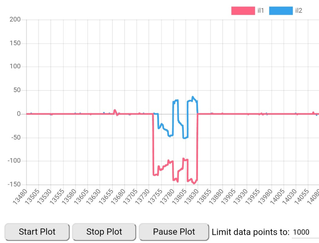
The PI regulator for d current has to transition very fast from negative to positive output when going into regen. Any lag in that will interrupt the field weakening process and allow excessive regen currents which then trip out the inverter.

Current fix:
When driving at high rpm come off the throttle slowly. If traffic doesn't allow for that, you're screwed

Planned fix:
I will introduce another ramp that comes in effect at high rpm that slowly brings on regen.

EDIT:
Actual fix: lower regenramp to 0.3
Just did a test drive and it is super smooth and has no problem transitioning between accleration and regen even at 7500 rpm :)
Support R/D and forum on Patreon: https://patreon.com/openinverter - Subscribe on odysee: https://odysee.com/@openinverter:9
johnspark
Posts: 264
Joined: Fri Apr 12, 2019 10:42 pm
Location: Adelaide, South Australia
Has thanked: 59 times
Been thanked: 48 times

Re: Testing FOC for synchronous motor

Post by johnspark »

An automatic tuning method may be:
Use (syncofs : axle speed) relationship FIRST.
Increment manualid until axle turns at syncofs = 0.
Inset manualid = 3 Amps (assuming this is the lowest current for axle to turn at measurable speed) @ syncofs= 0.
>Check direction of rotation, call it F.
Insert manualid = 3 Amps @ syncofs = 65535.
>Check direction of rotation call it -F or R.
Activate routine to search for where axle direction flips from F to R. May be something like:
(0, 3) = F
(65535,3)=R [65535,3]
(32000,3) = R [32000,3]
(16000,3) =R [16000,3]
(8000,3)=F [ 8000,3]
(8000+(16000-8000)/2,3)=R [12000,3]
(8000+(12000-8000)/2,3)=F [10000,3] axle speed noticeably slower. (We now have region between which direction flips).
STOP
Use (syncofs : manualid) relationship SECOND.
From left, search via (syncofs : manualid):
Start with last F value found, 10000.
syncofs = 10000.
In small steps: (steps of 10?)
Increment syncofs, increase manualid until axle turns for measurable speed
>Keep running this iteration until no further increase of manualid gives measurable axle speed, OR we have run out of current.
We should hear the axle rumbling now.
Increment syncofs until rumbling stops.
STOP
Tuning complete.
User avatar
johu
Site Admin
Posts: 6713
Joined: Thu Nov 08, 2018 10:52 pm
Location: Kassel/Germany
Has thanked: 369 times
Been thanked: 1543 times
Contact:

Re: Testing FOC for synchronous motor

Post by johu »

Anyone tested that method?

Onto todays news: for a while now I had the car vibrate at very low rpm either when regenning down and even when very slowly accelerating. So I have now modified the offset calibration again that is run in the first half second after starting the inverter. It now takes 16 samples of both currents and then uses the average as current sensor offset. This rules out any noise in the offset calibration and consequently there is less DC offset.
This hasn't completely eliminated vibration but it is now no longer disturbing unless you're perfectionist.
I have removed the standstill recalibration which was more or less a botch.

Will be part of the next release.
Support R/D and forum on Patreon: https://patreon.com/openinverter - Subscribe on odysee: https://odysee.com/@openinverter:9
m.art.y
Posts: 645
Joined: Sat Jun 06, 2020 6:54 pm
Location: UK/EU
Has thanked: 35 times
Been thanked: 32 times

Re: Testing FOC for synchronous motor

Post by m.art.y »

johu wrote: Sat Feb 08, 2020 1:16 pm Yes, no excitation needed, so rev2 board will work. Remove encoder pull-up resistors!
You mean model RMF44AC? That is centered at Vcc/2. Would be perfect if it runs on 3V3. Otherwise you have to divide 2.5->1.65 accurately because there is no offset-calibration in that mode.
One sin/cos per turn is ok, just set respolepairs=1
I am using same exact encoder now. Would you please elaborate more on your comment?
Do you mean voltage divider circuit to divide 2.5 to 1.65v? Do you mean there is no way to calibrate signal voltage offset and divider circuit is the only solution?

I have got the encoder plotting angle when I turn the motor but it only shows angle from around 120 to 240 degrees and not full 360 degrees? Thanks
User avatar
johu
Site Admin
Posts: 6713
Joined: Thu Nov 08, 2018 10:52 pm
Location: Kassel/Germany
Has thanked: 369 times
Been thanked: 1543 times
Contact:

Re: Testing FOC for synchronous motor

Post by johu »

m.art.y wrote: Sat Dec 12, 2020 1:54 pm Do you mean there is no way to calibrate signal voltage offset and divider circuit is the only solution?
Yes, because the sin/cos chip doesn't have a neutral state where it just outputs 2.5V on both pins. Unlike a resolver, when that's not excited the offset can be measured.
Support R/D and forum on Patreon: https://patreon.com/openinverter - Subscribe on odysee: https://odysee.com/@openinverter:9
arber333
Posts: 3563
Joined: Mon Dec 24, 2018 1:37 pm
Location: Slovenia
Has thanked: 134 times
Been thanked: 335 times
Contact:

Re: Testing FOC for synchronous motor

Post by arber333 »

johu wrote: Sat Oct 17, 2020 5:50 pm Anyone tested that method?

Onto todays news: for a while now I had the car vibrate at very low rpm either when regenning down and even when very slowly accelerating. So I have now modified the offset calibration again that is run in the first half second after starting the inverter. It now takes 16 samples of both currents and then uses the average as current sensor offset. This rules out any noise in the offset calibration and consequently there is less DC offset.
This hasn't completely eliminated vibration but it is now no longer disturbing unless you're perfectionist.
I have removed the standstill recalibration which was more or less a botch.

Will be part of the next release.
Will that be used for Sine also?
arber333
Posts: 3563
Joined: Mon Dec 24, 2018 1:37 pm
Location: Slovenia
Has thanked: 134 times
Been thanked: 335 times
Contact:

Re: Testing FOC for synchronous motor

Post by arber333 »

m.art.y wrote: Sat Dec 12, 2020 1:54 pm I am using same exact encoder now. Would you please elaborate more on your comment?
Do you mean voltage divider circuit to divide 2.5 to 1.65v? Do you mean there is no way to calibrate signal voltage offset and divider circuit is the only solution?

I have got the encoder plotting angle when I turn the motor but it only shows angle from around 120 to 240 degrees and not full 360 degrees? Thanks
Like i said in other thread just connect sin/cos direct without pullups and sensors should see rising edge +1.1V/-1.1V.
Now see what inverter says about this...

EDIT: Damn, now i forgot that ENC A and B pins AD cant measure negative values! Yes you need to provide correct pullup divider so that Sin/Cos signal will drain pins Enc A and B approximately to 0V when signal will be at negative -1.1V. This means you need approximately 2.2V divider. There is already 10K on the line. Now you need to provide 6K8 or 7K6 divider to get signal to 2V.
What i would do is remove those R130/R129. Then i would put 10K resistors in their place. Not needed, RLS outputs can drain more than 12mA current!
Then i would add 6K8 resistor across 1nF caps so you would get 2V signal.
Now try to measure your circuit when you rotate rotor. Should move from 0V to 2.2V approximately.
m.art.y
Posts: 645
Joined: Sat Jun 06, 2020 6:54 pm
Location: UK/EU
Has thanked: 35 times
Been thanked: 32 times

Re: Testing FOC for synchronous motor

Post by m.art.y »

johu wrote: Sat Dec 12, 2020 4:55 pm
m.art.y wrote: Sat Dec 12, 2020 1:54 pm Do you mean there is no way to calibrate signal voltage offset and divider circuit is the only solution?
Yes, because the sin/cos chip doesn't have a neutral state where it just outputs 2.5V on both pins. Unlike a resolver, when that's not excited the offset can be measured.
Does the shape of the angle plot curve matter? After removing R29 and R30 on prius V1c board I now get 0 to 360 degrees range on the plot curve. However the shape is very odd. I am using RLS encoder. Motor does not spin at all with manualid across a lightbulb but I hear a high pitched whine. And when I remove the lightbulb it pulls way way too much current from the battery - thin wire from my battery evaporated instantly. I even got HICUROFS2 error several times previously. I use settings as per video. Spins the motor in sine.

Image
Image

EDIT: I found why inverter was drawing too much current - I had forgotten to solder inductor on V1c board. Now I can add manualid without burning wires. I went up to 100 A manualid and if I turn the motor by hand into a differenr position sometimes I get a short nudge where motor turns a couple degrees and stops. Both phase and battery wires stays cold if I run it for a few seconds. Motor sounds like water is flowing inside it or something like that.
User avatar
johu
Site Admin
Posts: 6713
Joined: Thu Nov 08, 2018 10:52 pm
Location: Kassel/Germany
Has thanked: 369 times
Been thanked: 1543 times
Contact:

Re: Testing FOC for synchronous motor

Post by johu »

Looks odd. Please scope sin/cos signal while manually turning the motor. Disconnect the power cables of the motor for this test.
Support R/D and forum on Patreon: https://patreon.com/openinverter - Subscribe on odysee: https://odysee.com/@openinverter:9
m.art.y
Posts: 645
Joined: Sat Jun 06, 2020 6:54 pm
Location: UK/EU
Has thanked: 35 times
Been thanked: 32 times

Re: Testing FOC for synchronous motor

Post by m.art.y »

johu wrote: Mon Dec 14, 2020 12:08 pm Looks odd. Please scope sin/cos signal while manually turning the motor. Disconnect the power cables of the motor for this test.
Thank you. I did measure the outputs with a multimeter and COS is ranging from ~1.3 to ~4.6 V but SIN is only ~0.2 to ~0.5 V. So one of the signals is faulty. This encoder is designed to have a voltage range from 1.9 to 4.1 V on both signals. My question is if I get this encoder replaced will it work with openinverter? Does the sin/cos signal need to be precisely from 0 to 3.3V or can it be anywhere in that range? If a voltage divider reduces the signal to swing from 0.9 to 2.4 V or from 0.5 to 1.4 V would that still work?

As you have mentioned before the encoder is reacting a bit when I send some manualid to the motor (without the motor spinning). I could see signal shift instantly in the angle plot and also on the multimeter. Also there are some spikes at idle. Woul that cause it not to spin the motor correctly or at all? I attach the screenshot of the angle plot. The 'dip' in the signal is caused by manualid to the motor. Signal recovers once the manualid is stopped.
Image
User avatar
johu
Site Admin
Posts: 6713
Joined: Thu Nov 08, 2018 10:52 pm
Location: Kassel/Germany
Has thanked: 369 times
Been thanked: 1543 times
Contact:

Re: Testing FOC for synchronous motor

Post by johu »

The requirement for sin/cos is that they are centered around 1.65V (3.3/2) AND their peak-to-peak amplitude must be between 0.8V-3.3V - the more the better. So you need a voltage divider that achieves that. And of course you need to find out why sin doesn't have a proper swing. Maybe something is misaligned?
Support R/D and forum on Patreon: https://patreon.com/openinverter - Subscribe on odysee: https://odysee.com/@openinverter:9
m.art.y
Posts: 645
Joined: Sat Jun 06, 2020 6:54 pm
Location: UK/EU
Has thanked: 35 times
Been thanked: 32 times

Re: Testing FOC for synchronous motor

Post by m.art.y »

johu wrote: Tue Dec 15, 2020 12:46 pm The requirement for sin/cos is that they are centered around 1.65V (3.3/2) AND their peak-to-peak amplitude must be between 0.8V-3.3V - the more the better. So you need a voltage divider that achieves that. And of course you need to find out why sin doesn't have a proper swing. Maybe something is misaligned?
Openinverter also supports AB encoder with FOC tuning? Would any of these encoder configurations would work natively with openinverter without complicated modifications?

https://www.rls.si/eng/fileuploader/dow ... _sheet.pdf
arber333
Posts: 3563
Joined: Mon Dec 24, 2018 1:37 pm
Location: Slovenia
Has thanked: 134 times
Been thanked: 335 times
Contact:

Re: Testing FOC for synchronous motor

Post by arber333 »

m.art.y wrote: Tue Dec 15, 2020 10:09 pm
johu wrote: Tue Dec 15, 2020 12:46 pm The requirement for sin/cos is that they are centered around 1.65V (3.3/2) AND their peak-to-peak amplitude must be between 0.8V-3.3V - the more the better. So you need a voltage divider that achieves that. And of course you need to find out why sin doesn't have a proper swing. Maybe something is misaligned?
Openinverter also supports AB encoder with FOC tuning? Would any of these encoder configurations would work natively with openinverter without complicated modifications?

https://www.rls.si/eng/fileuploader/dow ... _sheet.pdf
No that would be ABZ encoder. But as far as I know no one has tried one of them with FOC only resolver. You would again be a test subject.
You really need to take a step back and select one way to run your motor and stick to it.

My opinion, if you are pressed for time I would ditch the unknown motor and select one that is proven to work.
m.art.y
Posts: 645
Joined: Sat Jun 06, 2020 6:54 pm
Location: UK/EU
Has thanked: 35 times
Been thanked: 32 times

Re: Testing FOC for synchronous motor

Post by m.art.y »

arber333 wrote: Wed Dec 16, 2020 12:02 am My opinion, if you are pressed for time I would ditch the unknown motor and select one that is proven to work.
Sadly that is not possible at the moment for many reasons. My only hope now is getting the encoder or some sort of resolver to work or even better getting a bit more speed out of sine firmware on that permanent magnet motor temporarily - that would win me some time and then I could take the time pressure off that project and do it right.
arber333
Posts: 3563
Joined: Mon Dec 24, 2018 1:37 pm
Location: Slovenia
Has thanked: 134 times
Been thanked: 335 times
Contact:

Re: Testing FOC for synchronous motor

Post by arber333 »

m.art.y wrote: Wed Dec 16, 2020 8:41 am Sadly that is not possible at the moment for many reasons. My only hope now is getting the encoder or some sort of resolver to work or even better getting a bit more speed out of sine firmware on that permanent magnet motor temporarily - that would win me some time and then I could take the time pressure off that project and do it right.
Dont count on the Sine firmware. It can cause all sorts of problems and generally is inefficient on PM motors.
You can try some early versions of FOC code which allowed me to drive Leaf motor, but caused really hard banging on regen. :? .
viewtopic.php?f=2&t=15&start=25#p410
m.art.y
Posts: 645
Joined: Sat Jun 06, 2020 6:54 pm
Location: UK/EU
Has thanked: 35 times
Been thanked: 32 times

Re: Testing FOC for synchronous motor

Post by m.art.y »

arber333 wrote: Wed Dec 16, 2020 10:28 am Dont count on the Sine firmware. It can cause all sorts of problems and generally is inefficient on PM motors.
You can try some early versions of FOC code which allowed me to drive Leaf motor, but caused really hard banging on regen. :? .
viewtopic.php?f=2&t=15&start=25#p410
Did these early FOC work without motor position sensing device - encoder or resolver? I don't need any regen I can turn if off. I only need to drive few hundred meters that is all I need!

EDIT:
I read through the thread and you did a good job but you seemed to have used a resolver. I don't have anything.. So that is why I am using sine because I need to run in sensorless mode.
arber333
Posts: 3563
Joined: Mon Dec 24, 2018 1:37 pm
Location: Slovenia
Has thanked: 134 times
Been thanked: 335 times
Contact:

Re: Testing FOC for synchronous motor

Post by arber333 »

m.art.y wrote: Wed Dec 16, 2020 10:32 am
arber333 wrote: Wed Dec 16, 2020 10:28 am
m.art.y wrote: Wed Dec 16, 2020 8:41 am Sadly that is not possible at the moment for many reasons. My only hope now is getting the encoder or some sort of resolver to work or even better getting a bit more speed out of sine firmware on that permanent magnet motor temporarily - that would win me some time and then I could take the time pressure off that project and do it right.
Dont count on the Sine firmware. It can cause all sorts of problems and generally is inefficient on PM motors.
You can try some early versions of FOC code which allowed me to drive Leaf motor, but caused really hard banging on regen. :? .
viewtopic.php?f=2&t=15&start=25#p410
Did these early FOC work without motor position sensing device - encoder or resolver? I don't need any regen I can turn if off. I only need to drive few hundred meters that is all I need!
You cant physically turn regen off on PM motors their excitation is from hardware - the magnets. ACIM motor turns into a block of iron when you remove excitaion, not so for PM. Here current flows back through IGBT diodes and causes motor bucking etc...
This is why you need resolver even if you freewheel the motor. Because controler is fighting the magnets and actually sending some current back to work against them.

https://leafdriveblog.wordpress.com/201 ... eaf-motor/
I actually used resolver from Leaf motor yes.
Jrod
Posts: 6
Joined: Wed Nov 13, 2019 3:43 am
Location: northern california
Been thanked: 2 times

Re: Testing FOC for synchronous motor

Post by Jrod »

I have a 1fv5139 generator motor basically ipm I need to install an encoder. Could someone chime in on the use of one of these.
INC-3-75-101001-SSI1-AC1-12-AN ; from Celera motion
User avatar
SciroccoEV
Posts: 370
Joined: Thu Oct 10, 2019 1:50 pm
Location: Luton UK
Been thanked: 15 times

Re: Testing FOC for synchronous motor

Post by SciroccoEV »

The VESC codebase will run sensorless if you really need to.
arber333
Posts: 3563
Joined: Mon Dec 24, 2018 1:37 pm
Location: Slovenia
Has thanked: 134 times
Been thanked: 335 times
Contact:

Re: Testing FOC for synchronous motor

Post by arber333 »

SciroccoEV wrote: Wed Dec 16, 2020 9:35 pm The VESC codebase will run sensorless if you really need to.
Or Lebowski with help of commutation UVW sensors in first couple of turns.
m.art.y
Posts: 645
Joined: Sat Jun 06, 2020 6:54 pm
Location: UK/EU
Has thanked: 35 times
Been thanked: 32 times

Re: Testing FOC for synchronous motor

Post by m.art.y »

johu wrote: Tue Dec 15, 2020 12:46 pm The requirement for sin/cos is that they are centered around 1.65V (3.3/2) AND their peak-to-peak amplitude must be between 0.8V-3.3V - the more the better. So you need a voltage divider that achieves that. And of course you need to find out why sin doesn't have a proper swing. Maybe something is misaligned?
I got a replacement encoder. I set up a divider by removing pull up resistors R29 and R30 and attaching 16.4 kOhms resistors over C27 and C28 on V1c Prius board. This gives me peak to peak voltage of ~0.9 V to ~2.9 V. How do I get it centered around 1.65 V? I also tried 20 kOhm resitors and I still wasn't able to spin the motor. Without a voltage divider but with R29 and R30 removed I measured peak of 3.7 V at C27 and C28.
Encoder signals when not connected to inverter and no resistors attached range from ~1.29 to 4.9 V.

Motor does not spin makes a very weird noise with some manualid applied. I did remove the encoder to see if the motor shaft does anything at all and I could observe very slight nudge of the motor shaft every time manualid is applied. Once manualid is stopped shaft relaxes back to it's former position.

https://mega.nz/file/pppiHQKD#OJPC5zu54 ... Y_5bbOp8tc

My motor is attached to the gearbox and drive shafts and also wheels. I tried increasing manualid and I went up to 150A. At that I sometimes got quite strong attempt to spin but very short. I also got motor to vibrate at 150 A manualid. I attach some current sensor plots from my attempts. Anything unusual?
Image
Image
glink
Posts: 30
Joined: Mon Mar 15, 2021 7:02 pm
Has thanked: 1 time
Been thanked: 4 times

Re: Testing FOC for synchronous motor

Post by glink »

I know this has been answered, but not able to find it.
Question is how to control the low speed using the FOC firmware? (Using 5.0 now, but same with previous version)
With my setup, I'm not able to start my Nissan Leaf motor from the Toyota Gen 3 inverter unless setting POT to 1300 (out of max 4095), and then it revs up to about 1400 RPM with no load.
I'm only using a LAB power supply and boosting it up to 80V through the buck/boost module.
Increasing POT over 1300 only gives 100 RPM extra. (That is OK, 80V will probably not enable more)
So back to the question, the FOC SW will not rev it down using the POT input, see plot. I need to set the direction to neutral to rev it down to 0.
Is this because I have no load? Too low voltage (80V)?
Input appreciated.
Also, after it spins down to 0, POT is 0 and forward is engaged, I can get it spinning again by turning the shaft by hand. POT=0 should be current = 0?
Attachments
plot.PNG
Isaac96
Posts: 656
Joined: Sat Oct 05, 2019 6:50 pm
Location: Northern California, USA
Been thanked: 2 times
Contact:

Re: Testing FOC for synchronous motor

Post by Isaac96 »

First I assume you've calibrated your potmin and potmax.
Second, spinning without throttle usually indicates an incorrect syncofs setting. Have you calibrated that yet?
User avatar
ZooKeeper
Posts: 507
Joined: Mon Mar 30, 2020 10:23 pm
Location: USA

Re: Testing FOC for synchronous motor

Post by ZooKeeper »

That sounds like the result one might get if the syncof setting is incorrect, has that procedure been completed?
Huebner VCU controlling a Gen2 Prius Inverter powering an MGR
"Talent is equally distributed but opportunity is not." - Leila Janah
glink
Posts: 30
Joined: Mon Mar 15, 2021 7:02 pm
Has thanked: 1 time
Been thanked: 4 times

Re: Testing FOC for synchronous motor

Post by glink »

Isaac96 wrote: Fri Mar 26, 2021 12:42 am First I assume you've calibrated your potmin and potmax.
Second, spinning without throttle usually indicates an incorrect syncofs setting. Have you calibrated that yet?
Thanks to both! Haven't calibrated anything, I do the POT adjustment with CAN communication. Potmin=0 Potmax=4095 Throtcur=1
No, I haven't gone through the procedure, as was leaning on this to be correct with syncofs=0: https://openinverter.org/wiki/Configura ... Leaf_Motor
If this is not correct and anyone has done the Nissan Leaf EM57 motor calibration, please share!

EDIT: You are definitely right, ran through the routine and came to syncofs of 16300, now starts at POT=1500 (of 4095), still straight up to 1400 RPM. All POT values below 1500 winds the motor down to 0, so progress at least! Thanks
Post Reply