Page 1 of 1
MG4 11kW Charger/DCDC (EP3CCU1130B)
Posted: Tue Oct 07, 2025 7:06 pm
by manny
Got a MG4 11kW charger to replace the MG ZS charger I have now. 3 phase 16A is more use to me than 1 phase 32A.
Found the HVDC an the AC connectors, the LVDC is the same as other MG chargers.
Started to collect info on the wiki :
https://openinverter.org/wiki/MG_ZS_Charger
I'm still looking for the coolant connectors. They look like a NW14 or NW16 quick connector but the measurements doesn't match.
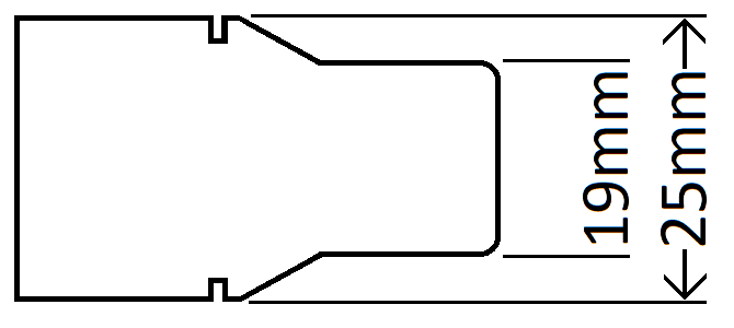
- MG4 coolantconnector.png (7.02 KiB) Viewed 4442 times
Nw14 is 17.5mm and NW16 is 22.3. So if any body has a idea what this is let me know.
The CAN communication on the charger uses CANFD so that's fun

Messages the charger sends out and the values I identified:
0x25E (12 bytes)
0x313 (48 bytes)
-PP status
-CP status
-CP duty cycle
0x314 (24 bytes)
-HV voltage
-HVIL
-External temp sensor
0x315 (24 bytes)
-DCDC output voltage
-AC L1 voltage
-AC L2 voltage
-AC L3 voltage
0x4E0 (8 bytes)
0x70E (8 bytes)
There is also a local CAN bus connected to the ESS and Electric Vehicle Communication Controller. There is no traffic on that bus.c
If there is someone with a MG4 and is willing to take a couple of CAN logs from charging sessions. Would be great.
Re: MG4 11kW Charger/DCDC (EP3CCU1130B)
Posted: Sun Jan 11, 2026 6:40 am
by m.art.y
manny wrote: ↑Tue Oct 07, 2025 7:06 pm
Got a MG4 11kW charger to replace the MG ZS charger I have now.
Hi, did you manage to get it working?

Re: MG4 11kW Charger/DCDC (EP3CCU1130B)
Posted: Sun Jan 11, 2026 12:12 pm
by manny
Working on it.
Got canlogs from someone on the Battery Emulator Discord.
Working on a test setup. And than I can start playing can logs.
Re: MG4 11kW Charger/DCDC (EP3CCU1130B)
Posted: Sun Mar 22, 2026 10:28 am
by manny
Have some success with the charger. Got the DCDC converter to kick in and charge the 12v battery to 14V.
In my setup I have the following connections.
The HVIL starts at the pin C4 this outputs a square wave at 50Hz. I have this connected to A1, C3 and D4
the CP and PP from the charger socket connect to the pins A3 and B3 (diagram shows F1 but thats linbus. The pinout table lists the CC as B3. And the lin diagram also shows F1)
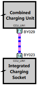
- LIN_diagram.PNG (13.84 KiB) Viewed 1577 times
The charging socket has a temperature sensor between pin E1 (5V source) and D2. I faked the sensor with a 100K resistor and it now reads 25C.
The PowerTrain CANFD is connected on pins C1 (H) and C2 (L)
12V power on pin H1 fused with 5A
GND on pin G4 and I have the case also connected to GND
Charger wakes up on connection of the charger or on canbus. It wakes on all messages send on the canbus but does not stay awake. When messages with the ID 0x4E0, 0x4E1 or 0x4F1 are send the charger stays awake for a couple of seconds after the messages stop.
The DCDC enables on message 0x08A not sure how the massages work and if the voltage is adjustable.
The CANFD messages are made up of smaller "sub messages". They are 12 bytes long the first 3 bytes are different in all messages may be a source ID and/or address or something like that. The fourth byte is 8 in all messages I think this is the number of data bytes. And than 8 data bytes in some messages the first data byte is a crc that is calculated over the 7 remaining data bytes. Using the calculator on crccalc.com it matches the crc_8/GSM-A crc. If a message has a crc the second databyte has a 4 bit counter
Added my dbc file and a log file. The log file is made with candump so sadly the timing is a bit rough. Maybe the timing can be reconstructed from a log from the charger
There is a lot of good info on the MG4 on
http://www.siteguru.co.uk/MG4/Manuals/
Re: MG4 11kW Charger/DCDC (EP3CCU1130B)
Posted: Mon Mar 23, 2026 3:44 pm
by davefiddes
I've done a little digging on the cooling connector. From what I can see it might be a NORMAQUICK V2 NW15 connector (
https://www.iq-parts-shop.com/en/normaq ... 69-mm.html). The drawings I can find aren't the greatest. From what I understand the NWxx connectors seem to be specified by the nominal internal diameter of the spigot in mm. Is the connector 15mm internal diameter?
Re: MG4 11kW Charger/DCDC (EP3CCU1130B)
Posted: Tue Mar 24, 2026 7:20 pm
by manny
Thanks for helping with the coolant connector hunt. it's doing my head in being unable to find the stupid connector.
Stuck the calipers in the spigot and the internal diameter is about 14mm.
When looking for nw15 I get confusing results.
Down the page there is a Technical drawing PDF
https://files.iq-parts.nl/NQ-V2-713-8015-015.pdf
In the "Service Repair Manual" it looks like a nw14 / nw16 style of connector but a different size
Re: MG4 11kW Charger/DCDC (EP3CCU1130B)
Posted: Tue Mar 24, 2026 7:36 pm
by jrbe
If you're willing to share the research it will help others,
https://openinverter.org/wiki/Coolant_Fittings
Re: MG4 11kW Charger/DCDC (EP3CCU1130B)
Posted: Tue Mar 24, 2026 9:09 pm
by manny
When digging through the mg4 manuals site I found the list of DTS's
http://www.siteguru.co.uk/MG4/Manuals/M ... 0v1.02.pdf
Would like to be able to read them. Using my kingbolen obd2 scanner I get nowhere.
looking at the data form kingbolen and sending it to a ID I got from the guy on battery emulator
when sending ID 0x7DF with data 02 01 00 00 00 00 00 00
I get a response from 0x7EC with data 06 41 00 08 00 00 00 AA
I am not very familiar with UDS, so more reading to do.
Re: MG4 11kW Charger/DCDC (EP3CCU1130B)
Posted: Sat Mar 28, 2026 6:03 pm
by manny
I am able to read DTC info with some help from AI.

In my previous post the can message I was sending was a OBD request.
ID 0x7DF with data 02 01 00 00 00 00 00 00
when requesting DTC info via OBD I got a negative response telling me service not supported.
when requesting DTC info via UDS I got a response telling me there are a 111 bytes of data.
request:
ID: 0x7E4 DATA: 03 19 02 FF 00 00 00 00
response:
ID: 0x7EC DATA: 10 6F 59 02 FF 1D 65 01
to get all the data a clear to send message needs to be send 15 times (0x6F(111) - 6 bytes in first message) / 7 = 15)
ID: 0x7E4 DATA: 30 00 00 00 00 00 00 00
The response:
0x7EC DATA: 106F5902FF1D6501
0x7EC DATA: 21281D6701201D68
0x7EC DATA: 22162F1D6A01281F
0x7EC DATA: 23A016201FA11720
0x7EC DATA: 241FA400201FAD00
0x7EC DATA: 25201FBE1C201FBF
0x7EC DATA: 261C201FC103201F
0x7EC DATA: 27C300201FC5962F
0x7EC DATA: 281FEE00201FEF87
0x7EC DATA: 296C321100283214
0x7EC DATA: 2A00203215002032
0x7EC DATA: 2B160020C0738840
0x7EC DATA: 2CC0748840C07588
0x7EC DATA: 2D40C1988728C293
0x7EC DATA: 2E8728D1118728D5
0x7EC DATA: 2F631620D8978728
The first byte is a index and the rest is data. After removing the indexes and spilt the data in 4 Byte codes, and the checking the codes in the DTC troubleshooting document I got this.
106F5902FF
1D650128 P1D65 01 B+/B- Connection Error
1D670120 P1D67 01 DCDC Active Discharge Timeout
1D68162F P1D68 16 DC/DC Input Voltage Below Threshold
1D6A0128 P1D6A 01 DCDC Mode Change Timeout Error
1FA01620 P1FA0 16 AC Voltage is too Low
1FA11720 P1FA1 17 AC Voltage is too High
1FA40020 P1FA4 00 Bus voltage of Power Factor Correction (PFC) Output is too Low
1FAD0020 P1FAD 00 High Voltage Interlock(HVIL) to BMS is Unlocked
1FBE1C20 P1FBE 1C OBC will Not Start Due to the Alternating Current (AC) Input is Overtime
1FBF1C20 P1FBF 1C OBC will Stop Due to the Alternating Current (AC) Input is Abnormal Shut Off
1FC10320 P1FC1 03 OBC will Stop Due to the Duty Cycle of Control Pilot (CP) PWM is Abnormal
1FC30020 P1FC3 00 OBC will Stop Due to the PFC MCU Shut Down the Power Loop through I/O Signal Output to the Main MCU
1FC5962F P1FC5 96 The temperature sensor in onboard charging socket is failure
1FEE0020 P1FEE 00 OffBoard Charging Socket Is Too High
1FEF876C P1FEF 87 LIN Communication Timeout
32110028 P3211 00 Onboard Charging Socket Electric Lock Fault
32140020 P3214 00 ACP to BMS Interlock(HVIL) is Unlocked
32150020 P3215 00 PDU to BMS Interlock(HVIL) is Unlocked
32160020 P3216 00 ESSPTC to BMS Interlock(HVIL) is Unlocked
C0738840 U0073 88 Control Module Communication Bus Off on Hybrid High Speed CAN
C0748840 U0074 88 Control Module Communication Bus Off on PT EXT CAN
C0758840 U0075 88 Control Module Communication Bus Off on BMS Cal CAN
C1988728 U0198 87 Lost Communication with TBOX/IAM
C2938728 U0293 87 Lost Communication With IMCU
D1118728 U1111 87 Lost Communication With Battery Management System(BMS)
D5631620 U1563 16 Battery Voltage Low
D8978728 U1897 87 Frame BMS_HSC1_FrP02 Timeout
There are some codes in the charger.

A Lot of these are from me dicking around with the charger. But this is great, it a lot easier if you know what the charger is not happy about
Re: MG4 11kW Charger/DCDC (EP3CCU1130B)
Posted: Sat Mar 28, 2026 7:18 pm
by m.art.y
manny wrote: ↑Sat Mar 28, 2026 6:03 pm
I am able to read DTC info with some help from AI.
Damien was able to get this charger start charging with just playing a CAN log back to it. Does it not work for you? You already caused some DTCs that are preventing it from charging?
Re: MG4 11kW Charger/DCDC (EP3CCU1130B)
Posted: Sun Mar 29, 2026 8:03 pm
by manny
m.art.y wrote: ↑Sat Mar 28, 2026 7:18 pm
Damien was able to get this charger start charging with just playing a CAN log back to it.
That is a charger from a MG ZS. The EP3CCU1130B is from a MG4 and uses CANFD
m.art.y wrote: ↑Sat Mar 28, 2026 7:18 pm
Does it not work for you? You already caused some DTCs that are preventing it from charging?
Probably

Re: MG4 11kW Charger/DCDC (EP3CCU1130B)
Posted: Sun Mar 29, 2026 8:32 pm
by manny
Because I was able to read the DTC's with Savvycan I went back to the Kingbolan OBD2 Scanner. With the scanner connected the same CAN messages were logged on Savvycan but without response from the charger. The messages looked identical same ID and same data.
The only difference CANFD. To test this I hacked together a arduino and 2 CAN interfaces one CAN and the other CANFD. That translated can to CANFD and back. It was a bit difficult to get de CANFD to send messages with 8 bytes as CANFD and not CAN.
After this success, the scanner was able to read the data from the charger and see freeze‑frame data and view live data.
That is a lot easier then decoding the data by hand.
Re: MG4 11kW Charger/DCDC (EP3CCU1130B)
Posted: Sun Mar 29, 2026 9:21 pm
by arber333
manny wrote: ↑Tue Oct 07, 2025 7:06 pm
Got a MG4 11kW charger to replace the MG ZS charger I have now. 3 phase 16A is more use to me than 1 phase 32A.
...
Please provide dimensions for later posting to wiki...
Re: MG4 11kW Charger/DCDC (EP3CCU1130B)
Posted: Mon Mar 30, 2026 7:12 am
by manny
arber333 wrote: ↑Sun Mar 29, 2026 9:21 pm
Please provide dimensions for later posting to wiki...
absolutely. I have bin working on the wiki information. will add pin-out, dimensions and weight.
The Wiki page is called "MG ZS Charger" is it possible tot change this to "MG Chargers" ?
Re: MG4 11kW Charger/DCDC (EP3CCU1130B)
Posted: Mon Apr 06, 2026 6:54 am
by manny
Success!!! I managed to charge the test battery.
Things that have changed since the previous post.
manny wrote: ↑Sun Mar 22, 2026 10:28 am
The charging connector has a temperature sensor between pin E1 (5V source) and D2. I recreated the sensor with a 100 kΩ resistor and now it shows 25°C.
There is a second temperature sensor connector on B2. So there is a second 100 kΩ resistor connected between B2 and D2. E1 is not a 5V source, but has been internally pulled to 5V. D2 is a ground connection.
One of the error codes related to the locking of the charging connector. The locking motor is connected to H3 and H4, and the feedback is on F4. There was a small voltage of 1.6 Volts on F4. With the OBD scanner connected and viewing live data of the locked status, I touched F4 to GND and the status changed to "locked".
While playing a CAN log, I managed to enable the EVSE, and after some time the battery started charging.
Now it is time to figure out which CAN messages are needed.
Re: MG4 11kW Charger/DCDC (EP3CCU1130B)
Posted: Mon Apr 06, 2026 9:58 pm
by manny
Used the OBD scanner to find the necessary can messages. While playing a log file I disabled the can messages one by one and than check the DTC's
Found the following message ID's per DTC:
U0146 ICC CPP GW (Integrated Communication Controller)(Charging Power Port)(Gateway Module)
U0151 SDM (Sensing and Diagnostic Module)
U0198 TBOX IAM (Communication Module) (In-car Application Module)
- 0x159
- 0x1A7
- 0x1F5
- 0x211
- 0x225
- 0x227
- 0x333
- 0x47E
- 0x4C0
U0293 IMCU (Intelligent Motor Control Unit)
U1111 BMS (High-voltage Battery Pack)
Re: MG4 11kW Charger/DCDC (EP3CCU1130B)
Posted: Tue Apr 07, 2026 12:57 pm
by tom91
very nice way of doing this, would be worth doing this for the other charger versions too. Helps narrow down what info maybe in the messages.
Re: MG4 11kW Charger/DCDC (EP3CCU1130B)
Posted: Tue Apr 07, 2026 5:38 pm
by Jack Bauer
That is very clever. I seem to have one of these chargers on the way from a sponsor
Re: MG4 11kW Charger/DCDC (EP3CCU1130B)
Posted: Mon Apr 13, 2026 9:21 pm
by manny
Got some control over the charger.
To get to that point I found that the charger needed 5 more ID's. There are 3 messages that wakeup the charger for longer than the rest of them. Not sure if they are really required. In the live data on the kingbolan scanner there are 2 interesting data points:
- BMS charging command
- BMS Main Relay Status
Looking at live data while playing a log file and wait for a change. Reverse the playback to change it back. Disable some ID's in the log file. And play forward again and look for the change. Repeat until you find the ID that causes the change.
BMS charging command is in the 0x15A message and BMS Main Relay Status is in 0x15B
Looking at the data I found numbers that corresponds to list in the live data
"MG4 EV UK Guided Fault Finding Live Data" PDF
BMS Operation State:
- Power-on
- Ready to travel
- Precharge for traveling
- Drive mode
- Civil charging ready
- Rapid charging ready
- Civil charging mode
- Rapid charging mode
- Rapid charging completed
- Civil charging completed
- Civil precharge
- Collision mode
- In equilibrium
- Failure
BMS charging command
- Default
- Charging enable
- Off
- Restart
- Wait
- Charging request
- Discharge request
- Heating request
- Discharge enable
While playing a log file filled to the ID's listed in my previous post. And running a script for the 0x15A and 0x15B messages I'm able to start and stop the charger. Also found the bits that control the DCDC converter in the 0x08A message. With it set to Work(BUCK on the kingbolan)it charges the 12V battery.
DCDC Mode Request
- Stand by
- Advance
- Work
- High voltage terminal discharge
Next up finding the limits for the charger. The MG ZS charger that I use now has DC voltage max, DC current max and AC current max. I assume that this charger has similar limits.
Re: MG4 11kW Charger/DCDC (EP3CCU1130B)
Posted: Tue Apr 14, 2026 9:06 pm
by manny
I got curious about V2L mode.
Connected my V2L adapter and instead of sending this sequence:
BMS charging command
- Default
- Charging request
- Charging enable
I send this:
BMS charging command
- Default
- Discharge request
- Discharge enable
And Bingo
Re: MG4 11kW Charger/DCDC (EP3CCU1130B)
Posted: Wed Apr 15, 2026 5:43 am
by Bigpie
Excellent job
Re: MG4 11kW Charger/DCDC (EP3CCU1130B)
Posted: Mon Apr 20, 2026 8:02 pm
by manny
With a lot of trial and error I found the max charge voltage. In the logs I got from a MG4 with a 64kwh battery the max voltage is set to 4.3V per cell. After talking to the guy that made the logs. He send me a new log form a MG4 with a 51Kwh LFP battery charged from 95% to 100%. To check if the max voltage gets changed at the end of the charge. Short answer NO and the max is set to 3.72V per cell. But my eye fell on the bytes next to the voltage. There was a value counting down.
Red is battery current
Blue is max charge current.
The BMS uses charge current to control the battery voltage.
At my test setup I set the max current to 1.5A and:
and set at 2.5A
To test all this I wrote a script file for Savvycan and a DBC file. Files end in .txt to be able to upload it to the forum just remove the .txt
