Page 1 of 3
Mainboard V3 FAQ
Posted: Tue Jan 28, 2020 5:07 pm
by johu
Re: Mainboard V3 FAQ
Posted: Tue Jan 28, 2020 8:02 pm
by StenOrl
johu wrote: ↑Tue Jan 28, 2020 5:07 pm
What is the minimum battery voltage for the engine to work with your board?
concerning the board there is no minimum voltage
The question was not like that - problems with translation !!! ... I want to know! - What is the minimum voltage when applying + _ contacts, and the voltage drops below 400 volts from the battery - For example, if the battery drops to 240 volts - will the engine work? Or not ????? ?? I know that when the battery drops to 320, the leaf board completely blocks the voltage supply and shows a low charge. Since the sheet microcontroller is removed from your board and uses only battery power, at what minimum voltage does the motor still have torque?
Re: Mainboard V3 FAQ
Posted: Tue Jan 28, 2020 8:14 pm
by johu
It will never drop out. But you can limit the low voltage with a parameter
Redacted the quote a bit...
Re: Mainboard V3 FAQ
Posted: Wed Feb 05, 2020 2:21 pm
by damian.lo
Hello,
Johannes, should I modify other parameters than offset for Leaf motor for setup V3 board+Leaf interface, which arrived from You?
For new setup probably yes, but if I take .json from your repository from the same setup in Touran should I also modify il1(2)gain, udcgain and ofs?
Then I can skip start2 and go directly to start 1 witch throttle and other signals?
Re: Mainboard V3 FAQ
Posted: Wed Feb 05, 2020 5:04 pm
by johu
Yes if you start with this
https://openinverter.org/wiki/Configura ... Leaf_Motor you can skip the basic calibration and only do your application setup.
Re: Mainboard V3 FAQ
Posted: Wed Feb 05, 2020 5:31 pm
by damian.lo
Thanks, now I remember that I was on wiki and saw those parameters

Should I also upgrade firmware from 4.66 to 4.71 with fully foc working or stay with old one until motor will work?
Re: Mainboard V3 FAQ
Posted: Wed Feb 05, 2020 7:24 pm
by johu
With FOC I'd say always grab the most recent one
Re: Mainboard V3 FAQ
Posted: Wed Feb 12, 2020 5:45 pm
by JaniK
If I order the mainboard first and then decice I want the leaf kit, do you sell the leaf addon boards separately?
Re: Mainboard V3 FAQ
Posted: Wed Feb 12, 2020 6:23 pm
by bennyr
Is there a maindboard V3 + leaf gen 1 kit available?
Re: Mainboard V3 FAQ
Posted: Wed Feb 12, 2020 8:52 pm
by johu
JaniK wrote: ↑Wed Feb 12, 2020 5:45 pm
If I order the mainboard first and then decice I want the leaf kit, do you sell the leaf addon boards separately?
Yes we could work that out
bennyr wrote: ↑Wed Feb 12, 2020 6:23 pm
Is there a maindboard V3 + leaf gen 1 kit available?
No, as the Gen 1 design is not proven I'm not selling it
Re: Mainboard V3 FAQ
Posted: Mon Mar 09, 2020 8:12 am
by konstantin8818
Johannes, in your info sheet for v3 board it is written that to provide 5V to encoder I need to deal with R1, R11 and R28 resistors. But on wiki there is info that there are pins providing 5V. I'm cofused. It would be really helpfull if you update this picture of board with pins named JP1.1 JP2.2 etc. on it.
Re: Mainboard V3 FAQ
Posted: Wed Mar 11, 2020 3:13 pm
by jerrykco
I took the liberty of Reading Johannes' Documentation here:
https://openinverter.org/wiki/Main_Board_Version_3
And adding info to this:
Let me know if I got something wrong. I will be glad to fix it.
Re: Mainboard V3 FAQ
Posted: Wed Mar 11, 2020 3:50 pm
by dima
Johannes can you allow ".drawio" or ".xml" file upload in Wiki?
I was going to upload the original diagram for public editing.
Original diagram can be edited with
https://draw.io
Re: Mainboard V3 FAQ
Posted: Thu Mar 12, 2020 6:42 am
by konstantin8818
Re: Mainboard V3 FAQ
Posted: Fri Mar 13, 2020 3:36 pm
by konstantin8818
As a complete newbie in electrinics, I try to get my head around this black wizardry and might ask stupid questions.
Now it is time for such question: There are 6 PWM outputs on V3 board, but it seems to me only high sides are connected to PWM inputs of the inverter and low sides are not connected to anything? at least those pins of BluePill on Damien's v2 board are hanging free. Or I missed something?
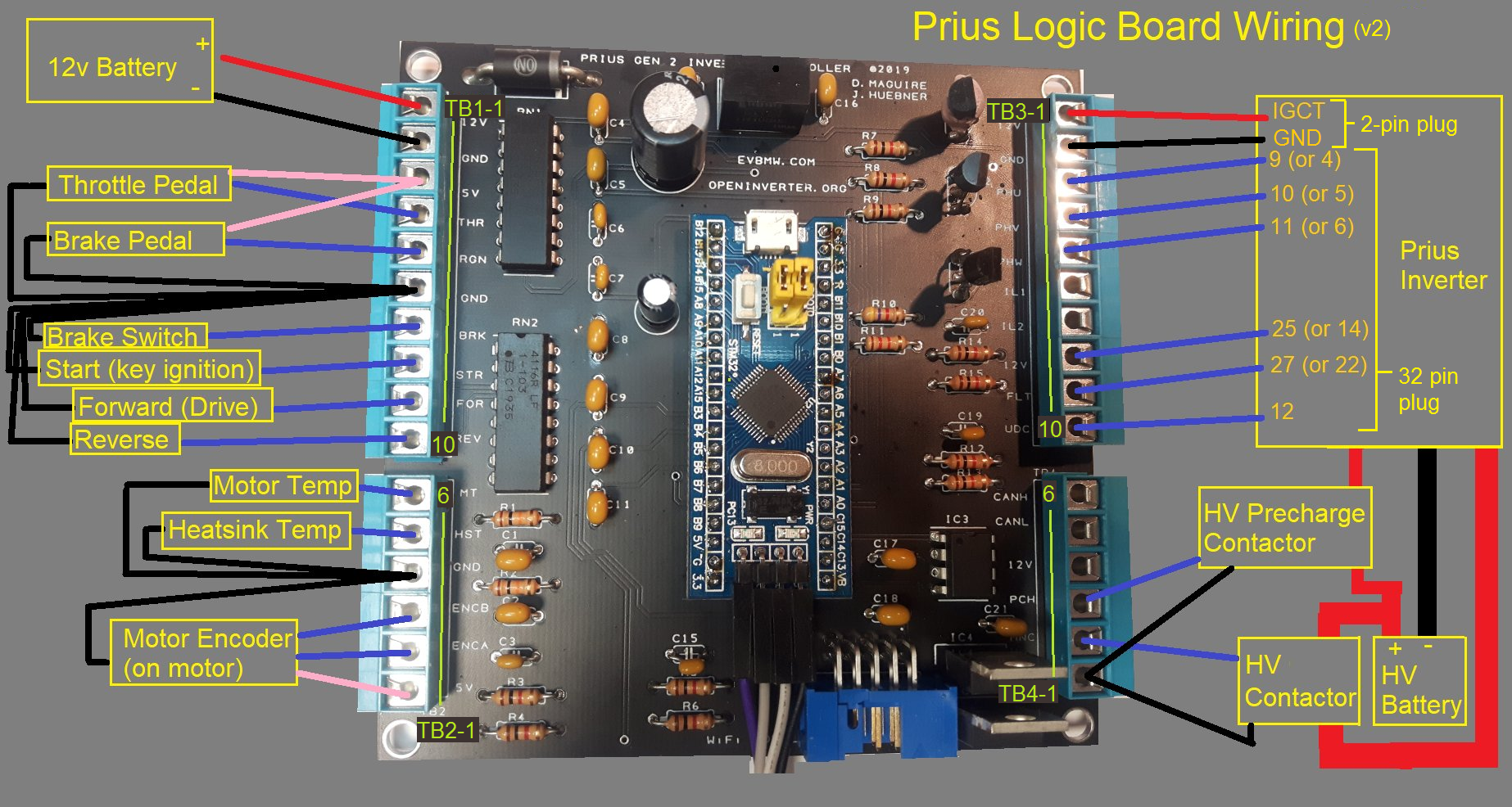
I try to figure out how to connect v3 board to prius gen2. And came to this:
Is this a correct way of connecting v3 board? Are there some other things need to be connected? Any suggestions?
Re: Mainboard V3 FAQ
Posted: Fri Mar 13, 2020 6:21 pm
by Yahha777
Нет - С тремя выводами никак работать не может, только 6 выводов. 3 на верхнее плечо и 3 на нижнее плечо. PWM1,2,3 BOT - нижнее плечо фаз, ты его не подключил на изображении. PWM1,2,3 TOP - это верхнее плечо - оно у тебя схематически подключено.
No - It can’t work with three conclusions, only 6 conclusions. 3 on the upper shoulder and 3 on the lower shoulder. PWM1,2,3 BOT - lower phase arm, you did not connect it in the image. PWM1,2,3 TOP - this is the upper arm - it is connected to you schematically.
Re: Mainboard V3 FAQ
Posted: Fri Mar 13, 2020 6:51 pm
by konstantin8818
Yahha777 wrote: ↑Fri Mar 13, 2020 6:21 pm
No - It can’t work with three conclusions, only 6 conclusions. 3 on the upper shoulder and 3 on the lower shoulder. PWM1,2,3 BOT - lower phase arm, you did not connect it in the image. PWM1,2,3 TOP - this is the upper arm - it is connected to you schematically.
So how Damien's board works then? Different type of signal? They both seems to utilise STM32 chip and same soft, I believe. There are only three phase wires goes in toyota gen2 inverter and fourth is ground.
Re: Mainboard V3 FAQ
Posted: Fri Mar 13, 2020 7:31 pm
by Yahha777
Ты чего-то явно не замечаешь. Принцип построения наверное всех 3-х фазных преобразователей частоты одинаков. С микроконтроллера выходит 6 выводов управления фазами, По 2 на фазу - один вывод управляет ключом задающим положительный потенциал на фазе - второй отрицательным потенциалом. И так в каждой фазе. В твоём случае нужно ещё задействовать PIN 4. 5. 6 на разъёме "Prius inverter pinout" они должны строго соответствовать фазировке с задействованными PIN 9. 10. 11. Фазы промаркированы U,V.W. К примеру - у тебя подключен вывод PWM1_TOP к выводу MG2 PWM U PIN9, соответственно PWM1_BOT к выводу MG1 PWM U PIN4. По аналогии PMW2 и PWM3.
You obviously don’t notice something. The principle of building probably all 3-phase frequency converters is the same. From the microcontroller, there are 6 phase control pins, 2 per phase - one pin controls the key that sets the positive potential in phase - the second negative potential. And so in each phase. In your case, you still need to use PIN 4. 5. 6 on the "Prius inverter pinout" connector, they must strictly correspond to the phasing with the PIN 9. 9. 11. 11. The phases are marked U, V.W. For example - you have connected the PWM1_TOP pin to the MG2 PWM U PIN9 pin, respectively PWM1_BOT to the MG1 PWM U PIN4 pin. Similar to PMW2 and PWM3.
Re: Mainboard V3 FAQ
Posted: Fri Mar 13, 2020 7:40 pm
by konstantin8818
Pins 4, 5, 6 are for MG1, which is completly separated from MG2
Re: Mainboard V3 FAQ
Posted: Fri Mar 13, 2020 7:54 pm
by johu
Prius power stage only needs the 3 positive pins and computes the negative ones itself
Re: Mainboard V3 FAQ
Posted: Fri Mar 13, 2020 8:01 pm
by Yahha777
johu wrote: ↑Fri Mar 13, 2020 7:54 pm
Prius power stage only needs the 3 positive pins and computes the negative ones itself
Согласен, посмотрел детально фото
https://openinverter.org/wiki/images/7/ ... ng_Map.png так и есть.
Re: Mainboard V3 FAQ
Posted: Fri Mar 13, 2020 8:27 pm
by konstantin8818
johu wrote: ↑Fri Mar 13, 2020 7:54 pm
Prius power stage only needs the 3 positive pins and computes the negative ones itself
Thank you! So basically my picture is correct? I've read wiki ten times but some things are above my understanding. There is a capacitor voltage output on prius socket, but I can't find if there is any incoming high voltage monitoring pin on v3 board.
Re: Mainboard V3 FAQ
Posted: Fri Mar 13, 2020 10:32 pm
by SciroccoEV
konstantin8818 wrote: ↑Fri Mar 13, 2020 8:27 pm
johu wrote: ↑Fri Mar 13, 2020 7:54 pm
Prius power stage only needs the 3 positive pins and computes the negative ones itself
Thank you! So basically my picture is correct? I've read wiki ten times but some things are above my understanding. There is a capacitor voltage output on prius socket, but I can't find if there is any incoming high voltage monitoring pin on v3 board.
A fuller explanation of the PWM signals would be that the Gen 2 Prius Intelligent Power Module uses complimentary inputs; When the signal is high one side of the half bridge is on, when the signal is low the other side is on*. The module takes care of the required dead-time between the two. This means you should set the dead-times to zero in the parameter to avoid distorting the waveform.
UDC is the input for DC bus voltage, which is pin 4 of JP7, I think. Normally a voltage sense board would be used, but the IPM is doing most of this for you. You'll just need to scale it's output to suit the STM32 ADC input.
*The only way to have both halves of the half bride off is to use the enable line and that affects all three half bridges in a given inverter (MG1 or MG2)
Re: Mainboard V3 FAQ
Posted: Sat Mar 14, 2020 7:42 am
by konstantin8818
SciroccoEV wrote: ↑Fri Mar 13, 2020 10:32 pm
UDC is the input for DC bus voltage, which is pin 4 of JP7, I think. Normally a voltage sense board would be used, but the IPM is doing most of this for you. You'll just need to scale it's output to suit the STM32 ADC input.
Thank you! That is more clear now.
So I need to provide needed voltage to inverter's bus bar, for example 360 Volts, and mesure what is coming out from 12 pin (inverter capacitor voltage) and scale it down to 3.3V for UDC pin, using basic dc-dc converter?
Re: Mainboard V3 FAQ
Posted: Sat Mar 14, 2020 8:41 am
by rikohm
" using basic dc-dc converter?"
In this case i think a simple resistor divider is the way to go, it gives you a linear scaling of the voltage.