Teensy 3.2 don't seem to be available anywhere at the moment. I plan to use a 4.0.
From @Tom91 in the simpbms thread, "I am working on a Teensy 4.0 Version with two can buses. I do not know if anyone ported the code over yet beyond my own testing." There was no indication when it would be available.
Outlander VCU - Rear inverter, Charger and BMS
-
aot93

- Posts: 212
- Joined: Mon Feb 15, 2021 5:45 pm
- Location: UK, West Sussex
- Has thanked: 8 times
- Been thanked: 48 times
Re: Outlander VCU - Rear inverter, Charger and BMS
Bigpie and Rstevens81 have an ESP based bms project.
https://github.com/jamiejones85/ESP32-BMS
https://oshwlab.com/EV-Team/spaceballs
As for porting to the 4.1 I took a quick look first guess is:
All the watchdog and other hardware related functions will need re-writing.
The CAN library needs changing to flexCAN_T4
That's just to get it to compile, testing would be needed.
There could well be more.. Tom would be the best person ask.
-
tom91

- Posts: 2417
- Joined: Fri Mar 01, 2019 9:15 pm
- Location: Bristol
- Has thanked: 209 times
- Been thanked: 573 times
Re: Outlander VCU - Rear inverter, Charger and BMS
The main thing to check is what if any:
- pwm outputs
- anlogue inputs
-
Drivelafrance
- Posts: 11
- Joined: Sat May 28, 2022 8:04 pm
Re: Outlander VCU - Rear inverter, Charger and BMS
Hi all,
Thanks for the advice. ESP 32 would be my preference I suppose given their price, availability and, if I remember correctly, I think the teensy 4.1 can be somewhat fragile?
Cheers
Thanks for the advice. ESP 32 would be my preference I suppose given their price, availability and, if I remember correctly, I think the teensy 4.1 can be somewhat fragile?
Cheers
-
elShankos

- Posts: 46
- Joined: Thu Jun 30, 2022 9:17 am
- Location: Cape Town
- Has thanked: 30 times
- Been thanked: 10 times
Re: Outlander VCU - Rear inverter, Charger and BMS
Hi there, I have been hunting for a SimpBMS but there don't seem to be any available from the online suppliers. I managed to get a few Teensy 3.2s from eBay - does anyone know if there is anyone selling the SimpBMS base board (without the Teeny 3.2) perhaps?royhen99 wrote: ↑Sat Aug 20, 2022 9:54 am Teensy 3.2 don't seem to be available anywhere at the moment. I plan to use a 4.0.
From @Tom91 in the simpbms thread, "I am working on a Teensy 4.0 Version with two can buses. I do not know if anyone ported the code over yet beyond my own testing." There was no indication when it would be available.
Re: Outlander VCU - Rear inverter, Charger and BMS
On the dash controller - what’s the need for connecting to the tiny 3v3 pad under the teensy? Does this just boost the strength of the 3v3 signal?
-
royhen99
- Posts: 261
- Joined: Sun Feb 20, 2022 4:23 am
- Location: N. Wiltshire. UK
- Has thanked: 22 times
- Been thanked: 133 times
Re: Outlander VCU - Rear inverter, Charger and BMS
From looking at the schematic and pcb layout I don't think it needs to be connected. It's an internal connection on the Teensy board and should really have a different net name, so that it does not get connected on the main pcb.
-
aot93
- Posts: 212
- Joined: Mon Feb 15, 2021 5:45 pm
- Location: UK, West Sussex
- Has thanked: 8 times
- Been thanked: 48 times
Re: Outlander VCU - Rear inverter, Charger and BMS
There should be no requirement to connect to any of the underside pins.
Unless you are looking at the VBatt which is used for the clock.
Unless you are looking at the VBatt which is used for the clock.
-
arber333
- Posts: 3571
- Joined: Mon Dec 24, 2018 1:37 pm
- Location: Slovenia
- Has thanked: 134 times
- Been thanked: 339 times
- Contact:
Re: Outlander VCU - Rear inverter, Charger and BMS
@aot93 Do you by any chance use any BMS trigger for battery protection in your code? I would like to use a limit torque command within lower SOC range. say from 20% to 15% SOC. Signal from BMS should take care of the first trigger for when car would go into turttle mode.
However I am not sure how to signal the second boundry when car should fully stop. Should this be time conditioned? Say you have 5min to go somewhere then no more torque, car is OFF!
Or would it be better to set hard boundries like 3.2V for turttle mode and 3.0V for empty from BMS CAN reports? That way when you reach bottom your car stays immobile unless you charge the battery.
-
aot93
- Posts: 212
- Joined: Mon Feb 15, 2021 5:45 pm
- Location: UK, West Sussex
- Has thanked: 8 times
- Been thanked: 48 times
Re: Outlander VCU - Rear inverter, Charger and BMS
So I experienced hard stop first hand the other day, I actually managed to run the battery to the lower limit, the outlander cells drop really quickly after about 3.7v
In my setup the BMS main contactor out is wired to a relay on the RSDN of the inverter, so it will shut down the drive system if any limit condition is met as per Tom's design.
On the VCU side i have a fairly crude de rating system based on the BMS rated discharge current and actual current received over CAN.
It works ok for me but I would like to look at a better / more comprehensive stratergy.
Code: Select all
    if (BMS_discurrent < currentact) // Decrese tourque if we are over current - Crude needs work..
    {
      torqueRequest -= 20;
      if (timer1000_1.check() == 1)
      {
      Serial.println("--!OVER CURRENT!--");
      }
      if (torqueRequest < 0)
      {
        torqueRequest = 0;
      }
}-
arber333
- Posts: 3571
- Joined: Mon Dec 24, 2018 1:37 pm
- Location: Slovenia
- Has thanked: 134 times
- Been thanked: 339 times
- Contact:
Re: Outlander VCU - Rear inverter, Charger and BMS
I see what you mean. You derate regen to 0 i see.aot93 wrote: ↑Sat Oct 29, 2022 9:15 am So I experienced hard stop first hand the other day, I actually managed to run the battery to the lower limit, the outlander cells drop really quickly after about 3.7v
In my setup the BMS main contactor out is wired to a relay on the RSDN of the inverter, so it will shut down the drive system if any limit condition is met as per Tom's design.
On the VCU side i have a fairly crude de rating system based on the BMS rated discharge current and actual current received over CAN.
It works ok for me but I would like to look at a better / more comprehensive stratergy.
But i will use RSDN only for those really dangerous moments as battery overheating or confirmed UV event.
DC contactor needs to stay closed for the event though. Very important as with field weakening at higher rpm you can break the inverter if your DC contactor opens!
For normal derating i would like to use a simple limit similar to what you use. Thanks.
-
aot93
- Posts: 212
- Joined: Mon Feb 15, 2021 5:45 pm
- Location: UK, West Sussex
- Has thanked: 8 times
- Been thanked: 48 times
Re: Outlander VCU - Rear inverter, Charger and BMS
Yes that's exactly how this works, BMS can only control RSDN directly not the contactors. We really don't want to open them under load!
Re: Outlander VCU - Rear inverter, Charger and BMS
Hi,
Very interesting Project. I ordered the PCB's allready
I read trough the .cpp file but i cannot find if there is a way to limit the current or torque by a parameter/setting or is this done by the throttle maps?
Very interesting Project. I ordered the PCB's allready
I read trough the .cpp file but i cannot find if there is a way to limit the current or torque by a parameter/setting or is this done by the throttle maps?
-
aot93
- Posts: 212
- Joined: Mon Feb 15, 2021 5:45 pm
- Location: UK, West Sussex
- Has thanked: 8 times
- Been thanked: 48 times
Re: Outlander VCU - Rear inverter, Charger and BMS
It's all done through the throttle maps - this is the best way i've found to tune the motor response. plus you get speed relative regen.
Re: Outlander VCU - Rear inverter, Charger and BMS
Ok, thanks. Can you explain me how to read the throttle map. i don't understand how to read it.
-
aot93
- Posts: 212
- Joined: Mon Feb 15, 2021 5:45 pm
- Location: UK, West Sussex
- Has thanked: 8 times
- Been thanked: 48 times
Re: Outlander VCU - Rear inverter, Charger and BMS
It works a bit like an ignition advance map on a petrol car.
It's a 2d array where a value is returned based on the throttle position (x axis) and speed of the motor (y axis)
This is used as an offset multiplier to the pedal position to give the torque request (before any ramping is applied) a higher number means more torque a negative is regen.
Here is a spreadsheet I use to build the tables, it might help.
 Throttle MAp 1.xlsx
- (31.16 KiB) Downloaded 235 times
Re: Outlander VCU - Rear inverter, Charger and BMS
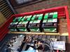
I’ve been playing with the dash control pcb and code to give us something more in keeping with the original Mini Speedo - @Tom91 helped with the code changes to suit his VCU but the PCB is still as @aot93 designed. I’m on my 3rd set of prototypes to mount the displays and stepper motor and it’s nearly there I think!
-
aot93
- Posts: 212
- Joined: Mon Feb 15, 2021 5:45 pm
- Location: UK, West Sussex
- Has thanked: 8 times
- Been thanked: 48 times
Re: Outlander VCU - Rear inverter, Charger and BMS
Nice, I think those little oleds look really good in the original instrument.
A tip if you get erratic needle behaviour is to edit the acceleration tables in SwitecX25.cpp the following values worked for me:
A tip if you get erratic needle behaviour is to edit the acceleration tables in SwitecX25.cpp the following values worked for me:
Code: Select all
static unsigned short defaultAccelTable[][2] = {
  {   20, 3500},
  {   50, 2000},
  {  100, 1500},
  {  150,  1000},
  {  300,  800}
};Re: Outlander VCU - Rear inverter, Charger and BMS
For my company I do a lot of bussines in China and also with the company Heltec. I own a ebike battery refurbish company.
They have a bms that can be used as single unit or modular from 8s to 240s and can also communicate with CANbus. If I can get the CAN communication file do you think you can implement it in the VCU? So it can control the bms, read temps, cell voltage etc.
They have a bms that can be used as single unit or modular from 8s to 240s and can also communicate with CANbus. If I can get the CAN communication file do you think you can implement it in the VCU? So it can control the bms, read temps, cell voltage etc.
-
aot93
- Posts: 212
- Joined: Mon Feb 15, 2021 5:45 pm
- Location: UK, West Sussex
- Has thanked: 8 times
- Been thanked: 48 times
Re: Outlander VCU - Rear inverter, Charger and BMS
With full documentation it is should be possible within the limits of either system.
Re: Outlander VCU - Rear inverter, Charger and BMS
ok, i will ask tomorrow if they will send me the CAN communication datasheet, and post it so you can check if it is possible
-
arber333
- Posts: 3571
- Joined: Mon Dec 24, 2018 1:37 pm
- Location: Slovenia
- Has thanked: 134 times
- Been thanked: 339 times
- Contact:
Re: Outlander VCU - Rear inverter, Charger and BMS
Can you post some datasheet for that BMS as well. I am also working on VCU master with esp32 chip. Could be usefull.
Re: Outlander VCU - Rear inverter, Charger and BMS
Hi,
Here is BMS CanBus datasheet
https://drive.google.com/file/d/1Gm6V8W ... sp=sharing
Spec sheet:
https://drive.google.com/file/d/1GmRgQk ... sp=sharing
although i think the price is not competitive enough with a proven system like the Orion.
The price of the product is $1406, excluding the collection line, freight and tax.
A set of products is a BMS master control module,2 slave machines, 1 800mm Harness,1 BMS-DCDC-24V,1 HALL-600A,1 Pre-charging resistance,1 anti-reverse diode and 3 Relay.