Page 5 of 5
Re: BMW LIM based CCS2 Controller
Posted: Wed Jun 22, 2022 11:56 pm
by asavage
alexbeatle wrote: ↑Wed Jun 22, 2022 5:51 pm
On the subject of the contactors. I'm trying to understand. Does the LIM economise the HV contactors?
From
earlier in this thread:
muehlpower wrote: ↑Thu Jun 03, 2021 9:32 am
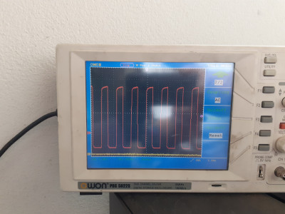
The Contactors are controlled by PWM, as jou can see at the OSZi, so it would be fine to use contactors without economizer, like the original Tesla Model 3.
Re: BMW LIM based CCS2 Controller
Posted: Thu Jun 30, 2022 10:37 pm
by alexbeatle
bitterandreal wrote: ↑Mon Oct 04, 2021 10:01 am
muehlpower wrote: ↑Sat Oct 02, 2021 2:29 pm
EV_Builder wrote: ↑Sat Oct 02, 2021 1:07 pm
Yeah; i agree the current VCU controller would be usable because it has 2 CAN interfaces. One for the LIM and one for the vehicle integration.
So that's covered.
In my setup there is a DUE that communicates with the LIM and my Tesla GEN3 charger via CAN 1. It also has the necessary 6 hardware lines for the charger and a simulation for the fuel filler flap for the LIM. It also queries the temperature at the CP and a button to cancel charging. The connection to the car, especially with the BMS, current sensor and cooling system is via CAN 0. This DUE is only in operation during charging, AC or DC, and also controls precharge and main contactors, which are switched by Damien's LDU board while driving.
I'm also planning to use a separate charge controller as a gateway between the vehicle CAN bus and the charging CAN bus.
How is your DUE code comparable with Damien's LIM code for the zombieVerter? And is it open source?
Jon volk's hardware would also be a perfect fit to have the voltage measure board and contactor driver included.
muehlpower uses Arduino the zombieVerter VCU uses libopencm3 and Jon volk wants to use STM HAL/FreeRTOS.
What are your considerations to chose one HAL/ framework above the other?
Sorry if a little off topic, but what controls the main contactors in this setup? They'd need to be closed for any of the charging and non-polarized to be able to interrupt charging, if I understand correctly.
Re: BMW LIM based CCS2 Controller
Posted: Fri Jul 01, 2022 8:03 am
by EV_Builder
That depends on design but what I have seen is key switches battery positive coil.
VCU or BMS switches battery negative coil en pre-charge.
Re: BMW LIM based CCS2 Controller
Posted: Fri Jul 01, 2022 8:15 am
by larsrengersen
In other words, in that setup 'nothing controls the main contactors'. The LIM just needs a "yes, ready to receive charge" from the car. How you get to that point is up to you and like EV_Builder says there are many possibilities.
I prefer the option where the BMS does contactor control (main+, main-, precharge and charger contactor).
Re: BMW LIM based CCS2 Controller
Posted: Sun Sep 18, 2022 3:58 am
by DkubusEV
If the two small 15.3Ohm dc charge contactors are in or at the main battery box or Junction then wouldn't it be safer to not require the "main contactors" to be energised? This way the length of cable exiting towards the dc charge port isn't "live" whilst driving (upto the dc contactors set-up/box etc. ??
Re: BMW LIM based CCS2 Controller
Posted: Sun Sep 18, 2022 2:19 pm
by muehlpower
In my case the motor is in the back, the battery box with the main contactors in the middle, AC charger with the fast DC contactors and the voltage sensing board in the front and the charge port in the front bumper. Auxiliary units branch off from the charger. When driving or charging, all devices are live. The advantage is that the DC-DC converter, A/C, battery heater, fan and water pump work while charging. As long as no 12V goes into the battery box, no 400V comes out either. That means you can work safely on the car. I have a lockable switch for that. that makes the TÜV happy. Actually, only the motor while charging is unnecessary under Voltage and the AC charger while driving.
Re: BMW LIM based CCS2 Controller
Posted: Sun Sep 18, 2022 5:26 pm
by larsrengersen
DkubusEV wrote: ↑Sun Sep 18, 2022 3:58 am
wouldn't it be safer to not require the "main contactors" to be energised?
I'd always ensure your BMS has the direct possibility to open the charger contactor in case of an emergency.
In my V1 high voltage design I had the following setup:
- Aux devices (DC/DC, aircon, heater) on in charge and discharge mode
- Inverter only energized in drive/discharge mode
- Charger only connected in charge mode
Now in my V2 high voltage design I do it a bit different:
- In discharge mode, aux devices on and inverter as well
- Charge mode = discharge mode + charger contactor
So now I also energize the inverter in charge mode (which is (ideally) not needed, but simplifies other things.
And in charge mode the BMS can open the charger contactor independently of whatever the DC contactors do.
Re: BMW LIM based CCS2 Controller
Posted: Wed Sep 21, 2022 4:50 am
by DkubusEV
larsrengersen wrote: ↑Sun Sep 18, 2022 5:26 pm
I'd always ensure your BMS has the direct possibility to open the charger contactor in case of an emergency.
In my V1 high voltage design I had the following setup:
- Aux devices (DC/DC, aircon, heater) on in charge and discharge mode
- Inverter only energized in drive/discharge mode
- Charger only connected in charge mode
Now in my V2 high voltage design I do it a bit different:
- In discharge mode, aux devices on and inverter as well
- Charge mode = discharge mode + charger contactor
So now I also energize the inverter in charge mode (which is (ideally) not needed, but simplifies other things.
And in charge mode the BMS can open the charger contactor independently of whatever the DC contactors do.
muehlpower wrote: ↑Sun Sep 18, 2022 2:19 pm
In my case the motor is in the back, the battery box with the main contactors in the middle, AC charger with the fast DC contactors and the voltage sensing board in the front and the charge port in the front bumper. Auxiliary units branch off from the charger. When driving or charging, all devices are live. The advantage is that the DC-DC converter, A/C, battery heater, fan and water pump work while charging. As long as no 12V goes into the battery box, no 400V comes out either. That means you can work safely on the car. I have a lockable switch for that. that makes the TÜV happy. Actually, only the motor while charging is unnecessary under Voltage and the AC charger while driving.
Thanks guys, really appreciate the descriptions of how you implemented the system safety with bms control over at least one of the contactors. I'm now thinking perhaps is best to use negative pack contactor (via fuse) to the DC charge contactor (inside battery junction box) so it (pack negative) is operated by bms and then have the DC charging positive contactor on battery side of main "positive pre charge contactor" so that I get the back-up safety of a bms controlled battery contactor (at negative) and without having to pre-charge and energise the main positive contactor. Thus leaving the inverter/motor isolated. My DC/DC is built into my on board charger and if I fit air-conditioning I guess I'll need one extra small contactor just to keep all "high voltage" and the related contactors inside the battery breakout-junction box. If I'm not possibly over complicating it but I'd rather not have voltage running anywhere that's not required during either driving or charging. Sincerely appreciate your input and ideas. Thanks guys.
Mike
Re: BMW LIM based CCS2 Controller
Posted: Wed Sep 21, 2022 5:48 am
by alexbeatle
larsrengersen wrote: ↑Fri Jul 01, 2022 8:15 am
In other words, in that setup 'nothing controls the main contactors'. The LIM just needs a "yes, ready to receive charge" from the car. How you get to that point is up to you and like EV_Builder says there are many possibilities.
I prefer the option where the BMS does contactor control (main+, main-, precharge and charger contactor).
Can an inverter get damaged if BMS drops contactors to it? I don't quite understand how, but there was a note on that somewhere here regarding Tesla SDU.
Re: BMW LIM based CCS2 Controller
Posted: Wed Sep 21, 2022 5:59 am
by larsrengersen
alexbeatle wrote: ↑Wed Sep 21, 2022 5:48 am
Can an inverter get damaged if BMS drops contactors to it? I don't quite understand how, but there was a note on that somewhere here regarding Tesla SDU.
Depends on the inverter. But yes, this applies to Tesla SDU and LDU and maybe more.
When the motor is spinning there is energy there and without the battery connected there is nowhere to can go.
Azure DMOC645 and Leaf inverter can handle this.
But this is a reason for my V2 design. VCU controls main + and main - and ensures drivetrain is disabled before opening contactors.
Re: BMW LIM based CCS2 Controller
Posted: Wed Sep 21, 2022 9:20 pm
by EV_Builder
Without a correct safety handshake this will happen indeed.
Re: BMW LIM based CCS2 Controller
Posted: Tue Apr 11, 2023 3:34 am
by asavage
I posted some info on a Plug-n-Charge alternative, in use by EVgo and Fastned, with MAC address implications:
viewtopic.php?p=55416#p55416
Re: BMW LIM based CCS2 Controller
Posted: Tue Jul 25, 2023 7:14 pm
by alexbeatle
muehlpower wrote: ↑Tue Jun 01, 2021 1:01 pm
i changed my circuit a little and now it's fine. The circuit is required to measure the voltage at the charging connector and to pass it on to the LIM
Sensing.png
I should probably post this here...

alexbeatle wrote: ↑Mon Jul 24, 2023 11:30 pm
What are minimum wire sizes on the HV and LV sides?
Re: BMW LIM based CCS2 Controller
Posted: Tue Jul 25, 2023 7:42 pm
by muehlpower
I would place the board near the HV contactors to avoid unnecessary HV lines running through the car. The cable cross section can be very small because only about 20mA flow through, but there should be sufficient mechanical strength.
so 0.35mm² to 0.5mm²
Re: BMW LIM based CCS2 Controller
Posted: Tue Aug 22, 2023 4:13 am
by alexbeatle
bitterandreal wrote: ↑Thu Oct 21, 2021 9:35 am
Absolutely agree on this. Very important function.
I thought the LIM pin 1B-15 (CHARGE_E) was a drive interlock signal but will change it in the schematics and in the wiki if it is not.
Any idea what is 1B-15 (CHARGE_E) for? Curious.
Re: BMW LIM based CCS2 Controller
Posted: Tue Aug 22, 2023 4:17 am
by asavage
We were guessing it was a hardware Drive Inhibit signal. It's noted as "not needed" in
the Wiki.
Re: BMW LIM based CCS2 Controller
Posted: Tue Aug 22, 2023 5:19 pm
by muehlpower
this is chrge enable
Re: BMW LIM based CCS2 Controller
Posted: Tue Aug 22, 2023 5:24 pm
by alexbeatle
Any advise on how to interlock drive when charging? The plan is to have LIM control both AC and DC charging. Using BMW i3 port without a cover.
muehlpower wrote: ↑Tue Aug 22, 2023 5:19 pm
this is chrge enable
Input to enable the LIM or output to enable the charger by the LIM?
Re: BMW LIM based CCS2 Controller
Posted: Tue Aug 22, 2023 8:58 pm
by muehlpower
output to enable the charger by Lim
Re: BMW LIM based CCS2 Controller
Posted: Fri Feb 23, 2024 1:48 am
by alexbeatle
Must the LIM module be at the end of the CANbus and no workaround?
Reads 120Ohm between the CAN-H and CAN-L.
Re: BMW LIM based CCS2 Controller
Posted: Fri Feb 23, 2024 8:03 am
by tom91
alexbeatle wrote: ↑Fri Feb 23, 2024 1:48 am
Must the LIM module be at the end of the CANbus and no workaround?
Reads 120Ohm between the CAN-H and CAN-L.
You answered your own question there. 120 ohm terminations are the ends of the bus.
Re: BMW LIM based CCS2 Controller
Posted: Fri Feb 23, 2024 4:13 pm
by asavage
I don't have a LIM anymore, but . . . is it possible to disable the LIM's termination? Desolder a resistor on the PCB?
Re: BMW LIM based CCS2 Controller
Posted: Fri Feb 23, 2024 4:41 pm
by alexbeatle
Cannot seem to locate the termination resistor. Right on the inputs it has the filter circuit (zeners and chokes), then then traces disappear into another layer.
Re: BMW LIM based CCS2 Controller
Posted: Fri Feb 23, 2024 5:47 pm
by royhen99
From photos here
viewtopic.php?p=19851#p19851 the termination is two 60R4 resistors on the reverse of the board.
Re: BMW LIM based CCS2 Controller
Posted: Fri Feb 23, 2024 11:53 pm
by alexbeatle
Cool. Looks like removing these two 60ohm resistors joined in series removed the CANbus termination, so the LIM can be put anywhere on the bus.
Thanks.
Edit.
Now that my CANbus is wired and I'm coding my VCU, just wanted to circle back and show that LIM CANbus is alive and talking, so nothing got damaged from removing the components.
