New Zombie user not getting LS outputs.

Topics relating to the ZombieVerter VCU
Post Reply
Alibro
Posts: 981
Joined: Sun Feb 23, 2020 9:24 am
Location: Northern Ireland
Has thanked: 368 times
Been thanked: 221 times
Contact:

New Zombie user not getting LS outputs.

Post by Alibro »

Hi guys, stupid question time and hopefully something silly I'm doing.
I'm testing my newly received Zombieverter by replacing the Leaf VCU in the car.
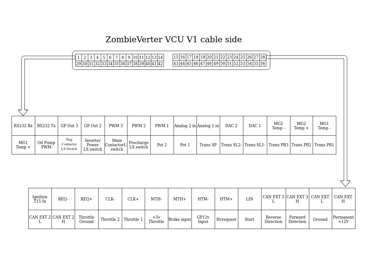
I think I have the parameters similar to Damiens from the Grey Goose but I'm not seeing any LS ouputs from any of the Pins 31 to 34 so no precharge, Inverter or negative contactor.
I've been able to calibrate the throttle without issues so am able to communicate with the VCU.

I don't have the HV connected as I wanted to see the outputs working correctly before connecting HV.
Is this possible?
I could do this with the Leaf VCU as it immediately sent the precharge output when T15 was turned on.
I have 12V on T15 through a switch and Start through another momentary switch.
Any suggestions?

Edit Things I've checked.
I've checked using Savvycan and when I turn on T15 the VCU starts spitting out CAN
I checked the ISA shunt is sending CAN and it is.
With both connected I can see CAN from both the shunt and VCU
I tried connecting a 20V battery to the shunt but Udc is still 0V so that need checking further.

I have to go out now but will try to post parameters later.
User avatar
tom91
Posts: 2389
Joined: Fri Mar 01, 2019 9:15 pm
Location: Bristol
Has thanked: 206 times
Been thanked: 561 times

Re: New Zombie user not getting LS outputs.

Post by tom91 »

What I am missing is:
Params
and Firmware version.

If there are no errors, negative will turn on and precharge output. Depending on config it will turn on the corresponding pins.
Creator of SimpBMS
Founder Volt Influx https://www.voltinflux.com/
Webstore: https://citini.com/
Alibro
Posts: 981
Joined: Sun Feb 23, 2020 9:24 am
Location: Northern Ireland
Has thanked: 368 times
Been thanked: 221 times
Contact:

Re: New Zombie user not getting LS outputs.

Post by Alibro »

Thanks mate
Granny sitting atm so can't do any more testing
Firmware is 2.22a web 2.0, Damien only shipped it a couple of weeks ago.

There are no errors but also no voltage showing on UDC even though I had a 20V battery connected to the ISA which was working fine with the Leaf VCU.
Screenshot from 2025-06-01 16-53-41.png
This screenshot was taken while the VCU was powered off but I don't think it has changed.
params.json
(2.14 KiB) Downloaded 8 times
I put a meter on the outputs but didn't get a GND on any of them.
User avatar
tom91
Posts: 2389
Joined: Fri Mar 01, 2019 9:15 pm
Location: Bristol
Has thanked: 206 times
Been thanked: 561 times

Re: New Zombie user not getting LS outputs.

Post by tom91 »

Go through your params.
https://openinverter.org/wiki/Zombiever ... pot_Values
"udcmin": 450 - this wont do

Also verify all input are working as they should. Specially if you say you are applying UDC but the ISA shunt is not being read by the zombie as it should.

edit: also use the spotvalue tab not that dashboard one. Also have a look at how to use the plot feature as this is helpful for looking at signals over time.
Creator of SimpBMS
Founder Volt Influx https://www.voltinflux.com/
Webstore: https://citini.com/
Alibro
Posts: 981
Joined: Sun Feb 23, 2020 9:24 am
Location: Northern Ireland
Has thanked: 368 times
Been thanked: 221 times
Contact:

Re: New Zombie user not getting LS outputs.

Post by Alibro »

Thanks mate, I'll report back later
I was using spot value as well but only sent the dashboard as the spot values wouldn't be much use with VCU powered off.
Alibro
Posts: 981
Joined: Sun Feb 23, 2020 9:24 am
Location: Northern Ireland
Has thanked: 368 times
Been thanked: 221 times
Contact:

Re: New Zombie user not getting LS outputs.

Post by Alibro »

Sorry I was so slow getting back but life got in the way.
I've been playing with the Zombie on the bench and can confirm I'm getting low side outputs as soon as I apply 12V to T15.
The Neg contactor pin goes low and stays low. The Precharge pin goes low but only for a second or two.
At this point I've nothing else connected but at least I can confirm I'm getting outputs.
Hopefully over the weekend I'll get time to install it in the car and learn a bit more.
Alibro
Posts: 981
Joined: Sun Feb 23, 2020 9:24 am
Location: Northern Ireland
Has thanked: 368 times
Been thanked: 221 times
Contact:

Re: New Zombie user not getting LS outputs.

Post by Alibro »

So I thought I had figured this out but now I'm back to getting no LS output on the Negative contactor pin 31

On Thursday while bench testing I connected permanent 12V and GND then T15 to +12V through a switch. When I flicked the switch I saw constant GND on Neg Contactor (pin 31) and 1 or 2 secs on Precharge (Pin 34) so I thought all was well.
I tried in the car again today and it was back to not working car so I disconnected everything except 12V, GND and T15 through a switch and tried again but it still didn't work.
Now I'm back on the bench with the same setup as before seeing the same issue so I've really only seen this working once.
I only have 12V permanent on pin 56, Gnd on pin 55 and am switching 12V +ve to T15 pin 15.
I've triple checked I'm getting voltage at T15 so am at a loss as to what I've done.
Have I made a stupid change to the parameters? Is there anything else required to see the neg contactor get a GND?
Thanks for any help guys.


Params attached.
params.json
(2.13 KiB) Downloaded 6 times
User avatar
tom91
Posts: 2389
Joined: Fri Mar 01, 2019 9:15 pm
Location: Bristol
Has thanked: 206 times
Been thanked: 561 times

Re: New Zombie user not getting LS outputs.

Post by tom91 »

Any errors in the spot values?
Please post all your spot values.

You double check all your inputs are showing up as they should?
Creator of SimpBMS
Founder Volt Influx https://www.voltinflux.com/
Webstore: https://citini.com/
Alibro
Posts: 981
Joined: Sun Feb 23, 2020 9:24 am
Location: Northern Ireland
Has thanked: 368 times
Been thanked: 221 times
Contact:

Re: New Zombie user not getting LS outputs.

Post by Alibro »

No errors but I see T15 status changing as I flick the switch on and off
PXL_20250607_152723082.jpg
PXL_20250607_152730543.jpg
PXL_20250607_152737031.jpg
PXL_20250607_152748602.jpg
PXL_20250607_152757174.jpg
User avatar
tom91
Posts: 2389
Joined: Fri Mar 01, 2019 9:15 pm
Location: Bristol
Has thanked: 206 times
Been thanked: 561 times

Re: New Zombie user not getting LS outputs.

Post by tom91 »

And you giving it a start 12V signal?

You can use the print function to save as pdf, or atleast you can for windows, easier to save.
Creator of SimpBMS
Founder Volt Influx https://www.voltinflux.com/
Webstore: https://citini.com/
Alibro
Posts: 981
Joined: Sun Feb 23, 2020 9:24 am
Location: Northern Ireland
Has thanked: 368 times
Been thanked: 221 times
Contact:

Re: New Zombie user not getting LS outputs.

Post by Alibro »

No nothing except T15 status
User avatar
tom91
Posts: 2389
Joined: Fri Mar 01, 2019 9:15 pm
Location: Bristol
Has thanked: 206 times
Been thanked: 561 times

Re: New Zombie user not getting LS outputs.

Post by tom91 »

You need a start signal to go into precharge.
Creator of SimpBMS
Founder Volt Influx https://www.voltinflux.com/
Webstore: https://citini.com/
Alibro
Posts: 981
Joined: Sun Feb 23, 2020 9:24 am
Location: Northern Ireland
Has thanked: 368 times
Been thanked: 221 times
Contact:

Re: New Zombie user not getting LS outputs.

Post by Alibro »

Thanks Tom
I had the start connected at some stage but must have had other settings wrong at the time.
With a bit of help from Kev39 I got them sorted and now the neg contactor pin goes low as expected when the start is pushed.
Alibro
Posts: 981
Joined: Sun Feb 23, 2020 9:24 am
Location: Northern Ireland
Has thanked: 368 times
Been thanked: 221 times
Contact:

Re: New Zombie user not getting LS outputs.

Post by Alibro »

For any other new user bench testing your Zombieverter to see how it works BEFORE using it to control a 400V system here are a few things I've figured out (with a little help). I'm sure there are other posts with better information than this one but hopefully It might help.

Link to main Zombiverter Wiki - https://openinverter.org/wiki/ZombieVerter_VCU
Link to a description of the parameters - https://openinverter.org/wiki/Parameter ... Parameters
Link to Pinouts - https://openinverter.org/wiki/images/7/ ... inout2.jpg

Minimum connections for testing.
12V permanent power.................................. - Pin 56
Gnd........................................................ - Pin 55
Ignition T15 in (Switched 12V +ve)................... - Pin 15
Start (momentary 12V in).............................. - Pin 52

Parameters required to get outputs for Neg Contactor and Precharge relay.
Note, be careful about saving parameters to flash, if you have a working setup then save it to flash and next time you power cycle the VCU those settings will be active again and likewise if you don't save them or save bad settings.

Potmin and Potmax need to be changed from defaults. Something like 165 and 1700 on potmin will be enough to get it working in single channel mode.
If you have selected Dual Channel then Potmin2 and Potmax2 should be approx doubled Potmin and Potmax but it seems hit and miss whether it will work without changing these.

Pin 31 labelled "Negative Contactor LS Switch" is actually a general purpose output pin labelled Out1Func in the Parameters. If this is set to anything else you may not get a Gnd to the Neg contactor when pushing the "Start" button but once again this can be hit and miss.

If you see UdcBelowUdcSw it just means the battery Voltage is too low to turn on the main (positive) contactor. As you're only bench testing without HV this makes sense. Setting UdcSW to 0V will remove this error but DO NOT save this to flash.

Beware!
If you change a parameter while T15 Status is applied you may see odd behaviour like contactors staying powered even after T15 is turned off.
Jacobsmess
Posts: 740
Joined: Thu Mar 02, 2023 1:30 pm
Location: Uk
Has thanked: 393 times
Been thanked: 110 times

Re: New Zombie user not getting LS outputs.

Post by Jacobsmess »

Alibro wrote: Sun Jun 08, 2025 2:12 pm
Potmin and Potmax need to be changed from defaults. Something like 165 and 1700 on potmin will be enough to get it working in single channel mode.
If you have selected Dual Channel then Potmin2 and Potmax2 should be approx doubled Potmin and Potmax but it seems hit and miss whether it will work without changing these.
Is this correct? I'd have thought pot min/max2 and pot min/max will depend on the pedal you're using and thus ranges will vary pedal to pedal. As I understand, calibration should occur for each setup on both pot1 and po2 min and max using the pot and pot2 value in the spot values with the throttle unpressed (min with additional 200) and pressed (max with 200 or s subtracted).
Alibro
Posts: 981
Joined: Sun Feb 23, 2020 9:24 am
Location: Northern Ireland
Has thanked: 368 times
Been thanked: 221 times
Contact:

Re: New Zombie user not getting LS outputs.

Post by Alibro »

Jacobsmess wrote: Sun Jun 08, 2025 3:58 pm Is this correct? I'd have thought pot min/max2 and pot min/max will depend on the pedal you're using and thus ranges will vary pedal to pedal. As I understand, calibration should occur for each setup on both pot1 and po2 min and max using the pot and pot2 value in the spot values with the throttle unpressed (min with additional 200) and pressed (max with 200 or s subtracted).
I was trying various parameters to see what would prevent the VCU going into Run mode and sending Gnd to the Neg contactor. I just wanted to get my head around how it worked before installing it in the car and leaving Potmin and Max as default was one of the causes.
Alibro
Posts: 981
Joined: Sun Feb 23, 2020 9:24 am
Location: Northern Ireland
Has thanked: 368 times
Been thanked: 221 times
Contact:

Re: New Zombie user not getting LS outputs.

Post by Alibro »

I know this has been mentioned else where but just in case others are going along the same path as me I'm mentioning it here.
I was struggling to get UDC voltage from the ISA shunt. I was only seeing 0V even though I confirmed I had CAN from the Shunt and VCU.
Turns out the Parameters are a bit confused and if the ISA shunt is connected to CAN1 you need to select CAN2 for the shunt in the Parameters page.
I did this and instantly saw voltage as expected.
Post Reply