Txs for sharing this. Assumptions are the mother of all...
I think I CAN, I think I CAN... Topic is solved
-
EV_Builder

- Posts: 1205
- Joined: Tue Apr 28, 2020 3:50 pm
- Location: The Netherlands
- Has thanked: 18 times
- Been thanked: 37 times
- Contact:
Re: I think I CAN, I think I CAN...
Converting an Porsche Panamera
see http://www.wdrautomatisering.nl for bespoke BMS modules.
see http://www.wdrautomatisering.nl for bespoke BMS modules.
-
Gregski

- Posts: 2743
- Joined: Tue Sep 14, 2021 10:28 am
- Location: Sacramento, California
- Has thanked: 500 times
- Been thanked: 946 times
- Contact:
Re: I think I CAN, I think I CAN...
so can I fix it? will you help me? if I was a Diode on this logic board, what would I look like? and where would I live?
please and thank you
please and thank you
"I don't need to understand how it works, I just need to understand how to make it work!" ~ EV Greg
-
celeron55

- Posts: 804
- Joined: Thu Jul 04, 2019 3:04 pm
- Location: Finland
- Has thanked: 38 times
- Been thanked: 136 times
- Contact:
Re: I think I CAN, I think I CAN...
You don't really need more than a multimeter with a diode check function to check the polarity of any HV power component.
If you get a diode voltage between 0.3V and 1.0V, that's a diode - no matter whether it's a real diode or just looks like one, it acts like one - don't connect your HV this way, there will be infinite current through the diode. In reality the "diode" is the reverse diodes inside the transistors that form a half bridge. In order to know more, type that into Google image search (not sponsored).
Then you switch your probes, and will see the diode check voltage rise from 0.0 to 1.0V and once it goes above, the multimeter will generally show its "open circuit" display. This means the multimeter just charged the capacitor inside the component to above its diode check voltage range and it's also possible to charge it more without issues.
The probe colors are now showing you the way you should connect the HV.
If the measurement does not act in this exact way, then you need to find another way, maybe a more high power one. There might be a bleed down resistor inside the component, or something weird going on.
And you of course should do this at the end you're about to connect to the battery, so that you notice any wiring errors (or have two errors that cancel themselves out... and 2 errors = 0 errors, obviously. Just be wrong enough, right?)
-
EV_Builder
- Posts: 1205
- Joined: Tue Apr 28, 2020 3:50 pm
- Location: The Netherlands
- Has thanked: 18 times
- Been thanked: 37 times
- Contact:
Re: I think I CAN, I think I CAN...
Post pictures we might get an idea. Fixing car stuff is not always easy since sometimes parts are not clearly marked etc...
Converting an Porsche Panamera
see http://www.wdrautomatisering.nl for bespoke BMS modules.
see http://www.wdrautomatisering.nl for bespoke BMS modules.
-
Gregski
- Posts: 2743
- Joined: Tue Sep 14, 2021 10:28 am
- Location: Sacramento, California
- Has thanked: 500 times
- Been thanked: 946 times
- Contact:
Re: I think I CAN, I think I CAN...
thank you, did couple threads aboveEV_Builder wrote: ↑Wed May 18, 2022 4:05 pmPost pictures we might get an idea. Fixing car stuff is not always easy since sometimes parts are not clearly marked etc...
"I don't need to understand how it works, I just need to understand how to make it work!" ~ EV Greg
-
arber333
- Posts: 3567
- Joined: Mon Dec 24, 2018 1:37 pm
- Location: Slovenia
- Has thanked: 134 times
- Been thanked: 337 times
- Contact:
Re: I think I CAN, I think I CAN...
I would advise you to continue working with CAN bus in the meantime.
Try to connect twisted pair with Canalyst, Microchip, Arduino DUE and Volt charger connected together. This will allow you to spy on your line with one device while you will be able to train to command with others.
Also as far as i know your battery BMS is also transmitting on its CAN bus. I just cant say at what speed.
-
EV_Builder
- Posts: 1205
- Joined: Tue Apr 28, 2020 3:50 pm
- Location: The Netherlands
- Has thanked: 18 times
- Been thanked: 37 times
- Contact:
Re: I think I CAN, I think I CAN...
Check the 3 partnumbers with the 3 legged back to two. (one is looks cut).
Those could be diodes. In one of your pictures I also see 12volts on the HV side? That's not to bad I would guess..
Converting an Porsche Panamera
see http://www.wdrautomatisering.nl for bespoke BMS modules.
see http://www.wdrautomatisering.nl for bespoke BMS modules.
Re: I think I CAN, I think I CAN...
Thanks for the documentation of your efforts. I have been wanting to dive into the CAN but so far am paralyzed. For instance, I'm not sure what files to download from https://github.com/collin80/SavvyCAN/re ... continuous and what to do with them. I use a windows computer primarily and know nothing about "compiling"
The CAN I want to reverse engineer lives in my Alta motorcycle. I have the OEM laptop (ubuntu) and dongle and can see the CAN data running through the Alta proprietary diagnostic software. I suppose I should use this computer going forward as it already set up for this. The Alta dongle is Lawicel based, which may or may not be important per my understanding.
The CAN I want to reverse engineer lives in my Alta motorcycle. I have the OEM laptop (ubuntu) and dongle and can see the CAN data running through the Alta proprietary diagnostic software. I suppose I should use this computer going forward as it already set up for this. The Alta dongle is Lawicel based, which may or may not be important per my understanding.
-
Gregski
- Posts: 2743
- Joined: Tue Sep 14, 2021 10:28 am
- Location: Sacramento, California
- Has thanked: 500 times
- Been thanked: 946 times
- Contact:
Re: I think I CAN, I think I CAN...
I can only comment on the Windows environment and in this environment the SavvyCAN software is a stand alone piece of code meaning nothing needs to be compiled nor installed, that's right you don't even need to install it or run setup or anything like that. You just download it from here:marengo wrote: ↑Wed Jun 08, 2022 12:44 pm Thanks for the documentation of your efforts. I have been wanting to dive into the CAN but so far am paralyzed. For instance, I'm not sure what files to download from https://github.com/collin80/SavvyCAN/re ... continuous and what to do with them. I use a windows computer primarily and know nothing about "compiling"
The CAN I want to reverse engineer lives in my Alta motorcycle. I have the OEM laptop (ubuntu) and dongle and can see the CAN data running through the Alta proprietary diagnostic software. I suppose I should use this computer going forward as it already set up for this. The Alta dongle is Lawicel based, which may or may not be important per my understanding.
https://github.com/collin80/SavvyCAN/re ... yCAN32.zip
then unzip or "extract it" and it will launch, now it won't work yet but the program will open up
what it needs beneath it is called GVRET. GVRET is not so much an application as it is firmware a lower level code that controls the hardware, this is the stuff you need Arduino IDE to compile onto a GVRET compatible hardware such as the Arduino DUE
hope this helps a little bit
"I don't need to understand how it works, I just need to understand how to make it work!" ~ EV Greg
-
Jack Bauer

- Posts: 3665
- Joined: Wed Dec 12, 2018 5:24 pm
- Location: Ireland
- Has thanked: 11 times
- Been thanked: 347 times
- Contact:
-
asavage

- Posts: 373
- Joined: Sat May 14, 2022 10:57 pm
- Location: Oak Harbor, Washington, USA
- Has thanked: 359 times
- Been thanked: 118 times
- Contact:
Re: I think I CAN, I think I CAN...
This is not addressed to Pete specifically, but rather to add to this thread's conversation around CAN termination resistors in general.
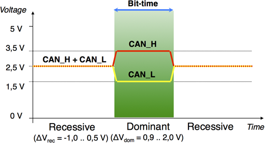
When the CAN lines are being actively driven, CANH is driven ~1v higher toward 3.5v, AND CANL is driven ~1v lower toward 1.5v, with a total differential voltage of approximately 2.0v.
When all CAN transceivers stop driving the lines (eg when changing from a 0/Dominant state to a 1/Recessive state), both CAN lines have to transition to as close to zero differential voltage as practical, and they have to make that transition within a defined timeframe. This is accomplished via the termination resistors!
If there is too much termination resistance -- eg only one termination resistor installed = 120 ohms across the CANL & CANH -- the bus cannot "reset" to differential voltage of 0v fast enough (or at all, if there is no termination at all), and data errors will occur because the next bit will be read as 0/Dominant when it should be 1/Recessive, which will eventually fail a CRC or other check (there is a CRC on EVERY frame). It affects the trailing-edge slew rate.
If there is too little termination resistance -- eg too many termination resistors (installed in parallel) -- then the CAN hardware drivers struggle to drive the differential voltage high enough, against the too-low impedance, it might take too long to rise to spec, and the next bit could/will be read as 1/Recessive instead of 0/Dominant. It affects the leading-edge slew rate.
In a nutshell, this is why having 60 ohms resistance across the CANL & CANH lines on a high-speed CAN bus is important. Ideally, this resistance is spread across two termination resistors, at the ends of the bus, but it's more important to have at or near the correct 60 ohms across the bus than the physical location of that resistance (though both are important design considerations). IOW, worry more about the value than the location of the CAN bus resistance.
Ref. https://en.wikipedia.org/wiki/CAN_bus#P ... ganization

Ref. https://www.can-cia.org/can-knowledge/c ... nsmission/
---
Having said the above . . . below is mere speculation . . .
So if Greg's Microchip black box tries to TX and drives the CAN bus to 0/Dominant but reads the resulting voltage as not quite high enough, it'll think it lost bus arbitration and will wait a few cycles for the bus to settle down, then try again. If the box tries to "send" a 1/Recessive (which involves not driving the bus to 2v differential voltage), but instead "reads" a 0, same thing. If this happens enough times, the transceiver reports an error, which SavvyCan presumably echoes back.
If I was a better writer, I could probably have said the above more concisely, but the Wikipedia CAN reference is pretty good, though it does require a time commitment to read through.
As a differential voltage signalling scheme, and unlike some other data buses that use termination primarily to damp signal reflections from the endpoints of the bus, the (high-speed, ISO 11898-2) CAN bus uses the 60 ohm bus impedance (2 * 120 ohm termination resistors, in parallel) to return both CAN lines to their nominal/passive/undriven state (typ. 2.5v) which equates to logical 1 and is referred to as Recessive statePete9008 wrote: ↑Wed May 11, 2022 3:26 pm The ideal is to have a termination at each end but as long as there is a termination somewhere you should be fine on a small network (few m of cable). Too many terminations reduce the signal level, possibly to the point where messages aren't received (but that would need quite a few extra terminations).
If you find a network is really sensitive to terminations there are probably other problems (such as high electrical noise) too.
In general if you are connecting to an existing network (e.g. to debug it) don't add a terminator on the dongle and keep the cables as short as possible. If you are creating a new network with the dongle at one end then add a termination on the dongle.
When the CAN lines are being actively driven, CANH is driven ~1v higher toward 3.5v, AND CANL is driven ~1v lower toward 1.5v, with a total differential voltage of approximately 2.0v.
When all CAN transceivers stop driving the lines (eg when changing from a 0/Dominant state to a 1/Recessive state), both CAN lines have to transition to as close to zero differential voltage as practical, and they have to make that transition within a defined timeframe. This is accomplished via the termination resistors!
If there is too much termination resistance -- eg only one termination resistor installed = 120 ohms across the CANL & CANH -- the bus cannot "reset" to differential voltage of 0v fast enough (or at all, if there is no termination at all), and data errors will occur because the next bit will be read as 0/Dominant when it should be 1/Recessive, which will eventually fail a CRC or other check (there is a CRC on EVERY frame). It affects the trailing-edge slew rate.
If there is too little termination resistance -- eg too many termination resistors (installed in parallel) -- then the CAN hardware drivers struggle to drive the differential voltage high enough, against the too-low impedance, it might take too long to rise to spec, and the next bit could/will be read as 1/Recessive instead of 0/Dominant. It affects the leading-edge slew rate.
In a nutshell, this is why having 60 ohms resistance across the CANL & CANH lines on a high-speed CAN bus is important. Ideally, this resistance is spread across two termination resistors, at the ends of the bus, but it's more important to have at or near the correct 60 ohms across the bus than the physical location of that resistance (though both are important design considerations). IOW, worry more about the value than the location of the CAN bus resistance.
Ref. https://en.wikipedia.org/wiki/CAN_bus#P ... ganization
Ref. https://www.can-cia.org/can-knowledge/c ... nsmission/
---
Having said the above . . . below is mere speculation . . .
Different CAN transceivers have slightly different internal specs for deciding when a differential voltage on the CAN lines is Dominant or Recessive, and it's possible that the Microchip unit is OK to read with your setup but not to transmit; with insufficient resistors (too little resistance) it might be reading some 0s when it is waiting for a 1 -- the CAN bus arbitration is predicated on only being able to transmit when someone else of higher priority is NOT transmitting, and that is defined by the Msg. ID (lower Msg. ID = higher priority). It's a bit dense to relate, but at the transceiver level, when there's a "window" in which a new frame can be transmitted (ie the bus traffic is at a sort of idle state momentarily), any transceiver can start transmitting. The way the prioritization scheme works is that the transceiver is required to monitor the bus as it's transmitting, and if it reads the wrong bit on the bus, it either loses priority arbitration, or it goes to error state (I'm simplifying here).Gregski wrote: ↑Sun May 15, 2022 5:53 pmI believe so because it reads messages just fine, which makes me think the high and low wires are connected properly and the termination is on, this guy has software controlled resistor terminator thingie and I tried it with both on and off, it is on in this case
So if Greg's Microchip black box tries to TX and drives the CAN bus to 0/Dominant but reads the resulting voltage as not quite high enough, it'll think it lost bus arbitration and will wait a few cycles for the bus to settle down, then try again. If the box tries to "send" a 1/Recessive (which involves not driving the bus to 2v differential voltage), but instead "reads" a 0, same thing. If this happens enough times, the transceiver reports an error, which SavvyCan presumably echoes back.
If I was a better writer, I could probably have said the above more concisely, but the Wikipedia CAN reference is pretty good, though it does require a time commitment to read through.
-
Pete9008
- Posts: 1801
- Joined: Sun Apr 03, 2022 1:57 pm
- Has thanked: 102 times
- Been thanked: 350 times
Re: I think I CAN, I think I CAN...
Great explanation, completely agreeasavage wrote: ↑Sun Jun 26, 2022 1:44 amAs a differential voltage signalling scheme, and unlike some other data buses that use termination primarily to damp signal reflections from the endpoints of the bus, the (high-speed, ISO 11898-2) CAN bus uses the 60 ohm bus impedance (2 * 120 ohm termination resistors, in parallel) to return both CAN lines to their nominal/passive/undriven state (typ. 2.5v) which equates to logical 1 and is referred to as Recessive statePete9008 wrote: ↑Wed May 11, 2022 3:26 pm The ideal is to have a termination at each end but as long as there is a termination somewhere you should be fine on a small network (few m of cable). Too many terminations reduce the signal level, possibly to the point where messages aren't received (but that would need quite a few extra terminations).
If you find a network is really sensitive to terminations there are probably other problems (such as high electrical noise) too.
In general if you are connecting to an existing network (e.g. to debug it) don't add a terminator on the dongle and keep the cables as short as possible. If you are creating a new network with the dongle at one end then add a termination on the dongle.
When the CAN lines are being actively driven, CANH is driven ~1v higher toward 3.5v, AND CANL is driven ~1v lower toward 1.5v, with a total differential voltage of approximately 2.0v.
When all CAN transceivers stop driving the lines (eg when changing from a 0/Dominant state to a 1/Recessive state), both CAN lines have to transition to as close to zero differential voltage as practical, and they have to make that transition within a defined timeframe. This is accomplished via the termination resistors!
If there is too much termination resistance -- eg only one termination resistor installed = 120 ohms across the CANL & CANH -- the bus cannot "reset" to differential voltage of 0v fast enough (or at all, if there is no termination at all), and data errors will occur because the next bit will be read as 0/Dominant when it should be 1/Recessive, which will eventually fail a CRC or other check (there is a CRC on EVERY frame). It affects the trailing-edge slew rate.
If there is too little termination resistance -- eg too many termination resistors (installed in parallel) -- then the CAN hardware drivers struggle to drive the differential voltage high enough, against the too-low impedance, it might take too long to rise to spec, and the next bit could/will be read as 1/Recessive instead of 0/Dominant. It affects the leading-edge slew rate.
In a nutshell, this is why having 60 ohms resistance across the CANL & CANH lines on a high-speed CAN bus is important. Ideally, this resistance is spread across two termination resistors, at the ends of the bus, but it's more important to have at or near the correct 60 ohms across the bus than the physical location of that resistance (though both are important design considerations). IOW, worry more about the value than the location of the CAN bus resistance.
I was more trying to make the point (probably fairly badly) that on a small network the termination is unlikely to be the problem so it makes more sense to concentrate on other things first.
I was just curious what the resistance limits might be so did a few sums:
Assuming a small network, lets say 5m. Now for reflections the worst case is transmission to the far end and back, so 5m x 2 x 5ns = 50ns. A bit time at 500kbps is 2us so with this length cable the first reflection will occur a 40th of a bit period in. Even allowing for multiple loop reflections we can pretty much ignore this it so accurately terminating the line is a nicety rather than a necessity. Also the location of the terminators is not important just the value.
As you say the other main reason the terminator is there is to provide a return to the recessive state in an acceptable time so the question is what is the maximum value of resistance that can do this. If we assume a cable capacitance of 60pF/m (screened twisted pair) then the total cable capacitance for a 5m length is 300pF. To allow for PCB trace capacitance, connectors, transceiver, etc lets call it a round 0.5nF. So how much resistance do we need to restore the recessive level in say 1/10th of a bit period. Bit period is 2us so 1/10th is 200ns so R needs to be no more than 400R (just calculated from t=RC so a 66% return to 0v state).
On the lower end most transceivers are rated to drive a 40R load, so in theory you could have 4 terminators on the bus and it still work - definitely not recommended though.
So on a 5m network it should work with a bus resistance of anywhere between 40R and 400R. In no way ideal but it should still work!
I actually have CAN bus running on my home BMS system which breaks all the rules, multiple 10-20m cable runs on a star topology and not a single 120R terminator anywhere (but I do have slew rate limited transceivers, lower data rates and distributed higher value terminators) - it works fine
To sum up on proper installs always do it right, 120R at each end on a daisy chain install will give the best system performance. On a small test install don't get too hung up on terminators, as long as you have at least one 120R on the network it should work - check other things first.
Edit - just for completeness, if the bus length is 10m the max R would be 200R and at 40m it would be 50R (pretty much the 60R for two 120R terminators). At this length the return trip propagation time is 40 x 2 x 5ns = 400ns which is getting close to the 1/4 bit period so we can no longer ignore transmission line effects. The transmission line effects mean that the transceivers do not 'see' the termination impedance/line capacitance any more, instead they 'see' the cable impedance. This means that further increases in length do not increase the capacitive loading on the transceiver, they just continue to see the cable impedance. There is therefore no change to the maximum value of the terminator as the line length continues to increase and the optimal terminator value is one which matches the characteristic impedance of the twisted pair (or 120R at each end!).
-
marcexec

- Posts: 184
- Joined: Tue May 14, 2019 12:52 pm
- Location: Dublin, Ireland
- Has thanked: 772 times
- Been thanked: 74 times
Re: I think I CAN, I think I CAN...
Enjoying this thread - did anyone have a look at the RP2040-based CANPico yet? https://kentindell.github.io/canpico
A motorcyclist is never late, Frodo Baggins. Nor is he early. He arrives precisely when he means to.
Getting started with Celeron55's iPDM56
My Suzuki RF400 build @ES
Honda IMA & Lebowski howto
Next event: Dublin Meet August 16th TOG Hackerspace
Getting started with Celeron55's iPDM56
My Suzuki RF400 build @ES
Honda IMA & Lebowski howto
Next event: Dublin Meet August 16th TOG Hackerspace
-
Gregski
- Posts: 2743
- Joined: Tue Sep 14, 2021 10:28 am
- Location: Sacramento, California
- Has thanked: 500 times
- Been thanked: 946 times
- Contact:
Re: I think I CAN, I think I CAN...
well it's been forever and a day since I played with this stuff, but I am finally ready to hook up the DC DC converter on my truck and was wondering if anyone has gotten it to work with a Teensy in a real world example, and since so much time has passed did they ever come out with a Teensy with a built in CAN Bus transceiver on it for compactability
and I know I have been out of the Teesnyduino game for a minute, but tell me this is wrong and they just forgot a decimal
and I know I have been out of the Teesnyduino game for a minute, but tell me this is wrong and they just forgot a decimal
"I don't need to understand how it works, I just need to understand how to make it work!" ~ EV Greg
-
asavage
- Posts: 373
- Joined: Sat May 14, 2022 10:57 pm
- Location: Oak Harbor, Washington, USA
- Has thanked: 359 times
- Been thanked: 118 times
- Contact:
Re: I think I CAN, I think I CAN...
I bought an SK Pang "Teensy 4.0 Triple CAN Bus Board With Two CAN 2.0B And One CAN FD Port" in April for $76 from Copperhill, and it's up to $80 today.
https://copperhilltech.com/teensy-4-0-t ... n-fd-port/
SK Pang offers a variety of Teensy 3.x & 4.x setups with CAN of various flavors. I looked around and didn't find a reasonably priced alternative for a package, though of course you can roll your own and add CAN tranceiver(s) to your own Teensy.
https://copperhilltech.com/teensy-4-0-t ... n-fd-port/
SK Pang offers a variety of Teensy 3.x & 4.x setups with CAN of various flavors. I looked around and didn't find a reasonably priced alternative for a package, though of course you can roll your own and add CAN tranceiver(s) to your own Teensy.
-
Gregski
- Posts: 2743
- Joined: Tue Sep 14, 2021 10:28 am
- Location: Sacramento, California
- Has thanked: 500 times
- Been thanked: 946 times
- Contact:
Re: I think I CAN, I think I CAN...
Whoa, and here I was about to show off by going with theasavage wrote: ↑Thu Jun 29, 2023 4:02 pm I bought an SK Pang "Teensy 4.0 Triple CAN Bus Board With Two CAN 2.0B And One CAN FD Port" in April for $76 from Copperhill, and it's up to $80 today.
https://copperhilltech.com/teensy-4-0-t ... n-fd-port/
SK Pang offers a variety of Teensy 3.x & 4.x setups with CAN of various flavors. I looked around and didn't find a reasonably priced alternative for a package, though of course you can roll your own and add CAN tranceiver(s) to your own Teensy.
Dual CAN-Bus adapter for Teensy 3.5, 3.6
"I don't need to understand how it works, I just need to understand how to make it work!" ~ EV Greg
-
asavage
- Posts: 373
- Joined: Sat May 14, 2022 10:57 pm
- Location: Oak Harbor, Washington, USA
- Has thanked: 359 times
- Been thanked: 118 times
- Contact:
Re: I think I CAN, I think I CAN...
I bought mine for a specific MiTM project, but later found that a MiTM solution for that issue wasn't needed, so it sits here on my desk 
Some of the CAN transceiver add-ons for Teensy have lousy reputations; SK Pang and Copperhill don't, which is why I bought this kit from them.
Some of the CAN transceiver add-ons for Teensy have lousy reputations; SK Pang and Copperhill don't, which is why I bought this kit from them.
Re: I think I CAN, I think I CAN...
I already had a USB CANdapter, used for programming Orion BMS, but I recently picked up an Adafruit Feather M4 CAN Express and also an RPI2040 CAN Bus Feather to play around with. I decided to install CircuitPython on the boards purely because I'd never used it and wanted to give it a try. Got both boards communicating with each other over CAN just to prove they worked. I was able to program the Feather to turn off the Engine Check Light, Oil Temp Warning Light, and manually control the rev counter on my 986 Boxster. My next step will be to get the Feather to listen for messages sent from the SDU openinverter board and map the motor power/amps to the rev counter. I might try to put the code for controlling the charger onto the same board or keep it separate, not sure yet. I like the idea of keeping things separate to limit impacts if 1 device fails.
I am aware that performance might be an issue here - CircuitPython uses an onboard interpreter so is slower than C++, and also, compared to the Teensy 4.1 CAN board, the M4 Feather and RPI2040 are relatively slow.
Does anyone have any experience using the M4 or RPI2040 board vs the Teensy, or using Ciruitpython over C++?
I should add that the Adafruit boards are £15-£20 and a lot easier to get hold of so were the ideal place to start even if it's a Teensy I end up using in production.
-
RetroZero
- Posts: 885
- Joined: Tue Oct 29, 2019 2:48 pm
- Location: France
- Has thanked: 558 times
- Been thanked: 53 times
- Contact:
Re: I think I CAN, I think I CAN...
I hate to say but I just ordered 2 can tranceiver thingies , some cables and breakout board, a sd card breakout board to hook up a STM Nucleo board and hope to start asking lots of stupid questions.
-
Gregski
- Posts: 2743
- Joined: Tue Sep 14, 2021 10:28 am
- Location: Sacramento, California
- Has thanked: 500 times
- Been thanked: 946 times
- Contact:
Re: I think I CAN, I think I CAN...
that's the spirit, you got this !!!
"I don't need to understand how it works, I just need to understand how to make it work!" ~ EV Greg
-
Gregski
- Posts: 2743
- Joined: Tue Sep 14, 2021 10:28 am
- Location: Sacramento, California
- Has thanked: 500 times
- Been thanked: 946 times
- Contact:
Re: I think I CAN, I think I CAN...
well it's been a while but I think I'm ready to get back on this horse, and troubleshooting the BMW Safety Box (aka contactor box) the other day, yes another CAN Bus speaking animal, with my friend who programs robotic arms and such, he asked how come we are sending CAN commands over and over again, I said what do you mean, and he said: "that's not how CAN works" implying he would only send a command once, cause that's all you have to do, so I am ready to start a thumb wrestling battle over this if you are
so i checked the B.A.F. for beepness and it beeped, so that's a good fuse
then I checked the capacitors for zeroness and they showed close to nothing aka 0.1 so that's good as well
so i checked the B.A.F. for beepness and it beeped, so that's a good fuse
then I checked the capacitors for zeroness and they showed close to nothing aka 0.1 so that's good as well
"I don't need to understand how it works, I just need to understand how to make it work!" ~ EV Greg
-
asavage
- Posts: 373
- Joined: Sat May 14, 2022 10:57 pm
- Location: Oak Harbor, Washington, USA
- Has thanked: 359 times
- Been thanked: 118 times
- Contact:
Re: I think I CAN, I think I CAN...
Maybe in robotics-land you can send a command once and be done, but in automotive-land, modules expect you to repeat yourself often, and if they don't hear from you, they assume something bad happened to you and they stop sending you money.
Hence, we have code that has 10ms loops, 50ms loops, 100ms loops, etc. to send some things over and over as long as we want something to continue happening.
Hence, we have code that has 10ms loops, 50ms loops, 100ms loops, etc. to send some things over and over as long as we want something to continue happening.
-
EV_Builder
- Posts: 1205
- Joined: Tue Apr 28, 2020 3:50 pm
- Location: The Netherlands
- Has thanked: 18 times
- Been thanked: 37 times
- Contact:
Re: I think I CAN, I think I CAN...
Well in robotics the same applies.
To compare you need for example a robot with IO or 2 robots which need to work together.
I'm pretty sure that you want to stop your robot quick (and maybe home position it) if you stop receiving position messages from the other. (Not smart to keep moving without knowing where your colleague is .
.
Same for an IO station. You want to be sure the gripper or what ever tool you have is responding and is sane. While running the process.
So also in robotics broadcasting can be needed and useful.
To compare you need for example a robot with IO or 2 robots which need to work together.
I'm pretty sure that you want to stop your robot quick (and maybe home position it) if you stop receiving position messages from the other. (Not smart to keep moving without knowing where your colleague is
Same for an IO station. You want to be sure the gripper or what ever tool you have is responding and is sane. While running the process.
So also in robotics broadcasting can be needed and useful.
Converting an Porsche Panamera
see http://www.wdrautomatisering.nl for bespoke BMS modules.
see http://www.wdrautomatisering.nl for bespoke BMS modules.
-
RetroZero
- Posts: 885
- Joined: Tue Oct 29, 2019 2:48 pm
- Location: France
- Has thanked: 558 times
- Been thanked: 53 times
- Contact:
Re: I think I CAN, I think I CAN...
Whilst you thumb wrestle, I'll just look at my thumbs and ask them to move. I was so chuffed to get lots of little packages, I forgot 2 small but essential components......120 Ohm resistors. Now to visit my favorite website again. I am just setting this up and doing backround research when possible to understand what I am supposed to do. Even got a diagnostic plug for when I graduate.
Edit, then I looked at the tranceivers again and my thumbs said, check the resistance accross the CAN-H and CAN-L - 118 Ohms. Oh, and there's a little black thingy resistor hiding on the board, so looks like we're set to go switch on Nucleo ( ) This could be the beginning of the end.
Edit g is this better?
Edit, then I looked at the tranceivers again and my thumbs said, check the resistance accross the CAN-H and CAN-L - 118 Ohms. Oh, and there's a little black thingy resistor hiding on the board, so looks like we're set to go switch on Nucleo (
Edit g is this better?
- Attachments
-
-
asavage
- Posts: 373
- Joined: Sat May 14, 2022 10:57 pm
- Location: Oak Harbor, Washington, USA
- Has thanked: 359 times
- Been thanked: 118 times
- Contact:
Re: I think I CAN, I think I CAN...
Tip: if you edit your image with something other than your phone, then save it, it'll likely reset the EXIF rotation tag to something more sane, so when people open the uploaded image, it doesn't suddenly rotate 90°.
It's a browser-honoring-the-standard thing.
It's a browser-honoring-the-standard thing.