Small drive unit inverter teardown and repair
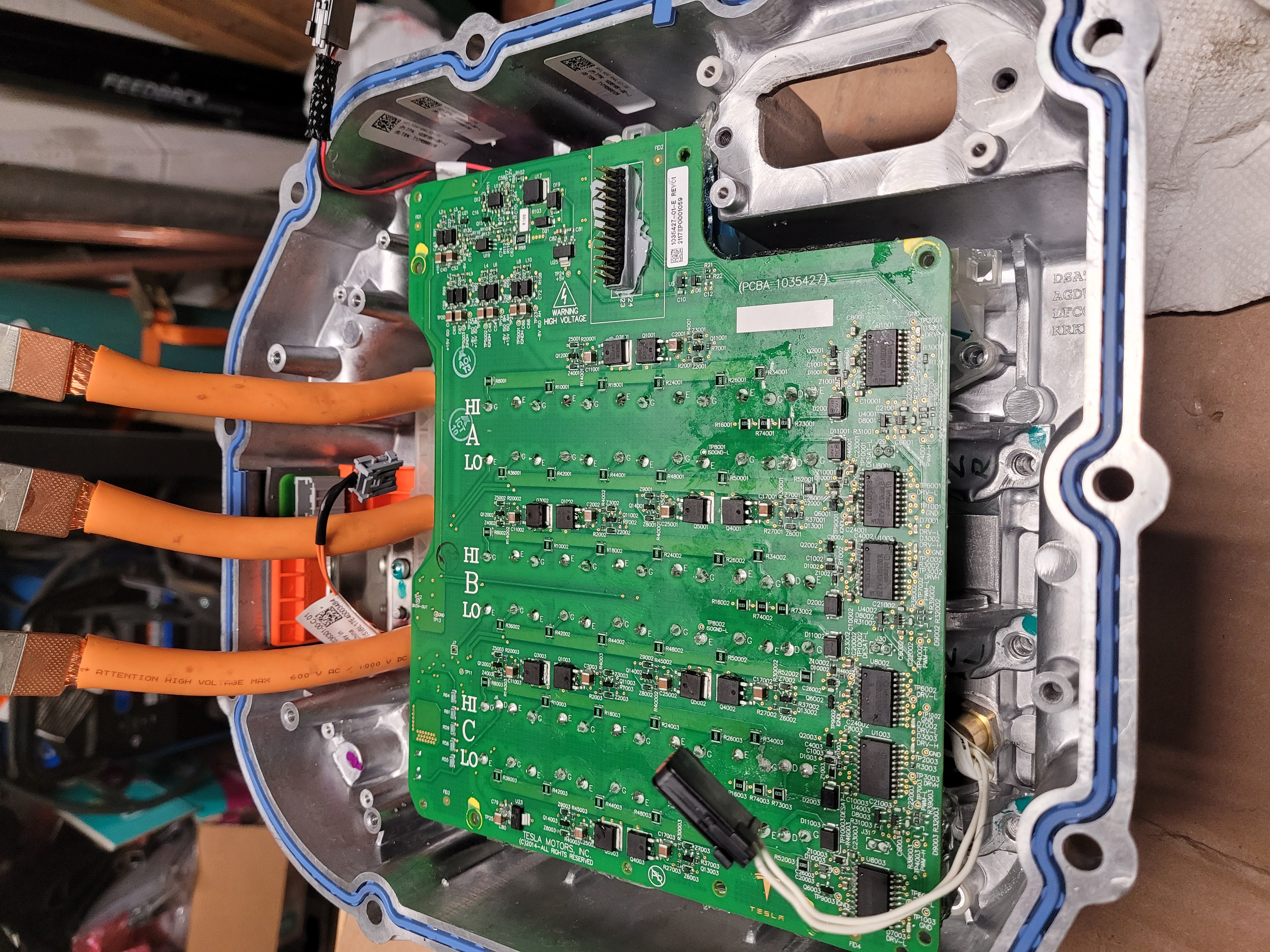
I got the plastic and goo off, but can't figure out how to get past to the power stage.
I fried two legs.
http://www-personal.umich.edu/~siegeljb ... 223414.jpg
1988 Porsche 911 targa with warp11 motor. Soon to be Tesla SDU.
- catphish
- Posts: 955
- Joined: Fri Oct 08, 2021 11:02 pm
- Location: Dorset, UK
- Has thanked: 94 times
- Been thanked: 179 times
Re: Small drive unit inverter teardown and repair
I'm afraid I don't know how to disassemble the power stage, but I'm interested to know - how did you damage it?
Re: Small drive unit inverter teardown and repair
Embarrassed, but by flashing the firmware of the openinverter with HV power applied. I was testing contractors and forgot that I left power on. That was an expensive mistake.
1988 Porsche 911 targa with warp11 motor. Soon to be Tesla SDU.
- catphish
- Posts: 955
- Joined: Fri Oct 08, 2021 11:02 pm
- Location: Dorset, UK
- Has thanked: 94 times
- Been thanked: 179 times
Re: Small drive unit inverter teardown and repair
Makes sense, thanks, definitely something to be careful of! By the way you've marked this thread as resolved (you ticked my reply), you should probably undo that since nobody has answered your question.
Re: Small drive unit inverter teardown and repair
Thanks,
Fat fingers on my phone.
This patent is instructive... but doesn't really tell me how to get things apart...
US10199804B2
https://patents.google.com/patent/US101 ... 10199804B2
Fat fingers on my phone.
This patent is instructive... but doesn't really tell me how to get things apart...
US10199804B2
https://patents.google.com/patent/US101 ... 10199804B2
1988 Porsche 911 targa with warp11 motor. Soon to be Tesla SDU.
Re: Small drive unit inverter teardown and repair
To remove the plastic cover and Goo I put 4 wood screws through the cover directly over the 4 torx heads and turned the screws to remove the plastic while liberally applying heat with a heatgun.
1988 Porsche 911 targa with warp11 motor. Soon to be Tesla SDU.
- EV_Builder
- Posts: 1199
- Joined: Tue Apr 28, 2020 3:50 pm
- Location: The Netherlands
- Has thanked: 16 times
- Been thanked: 34 times
- Contact:
Re: Small drive unit inverter teardown and repair
Pictures would help massively...
Converting an Porsche Panamera
see http://www.wdrautomatisering.nl for bespoke BMS modules.
Re: Small drive unit inverter teardown and repair
I'll stick a few pictures here.
http://warpedporsche.blogspot.com/2022/ ... n.html?m=1
Looks like it's still held by the power inlets, can't access the bolts and it looks like a purple ring locks the power pole in place, but I can't figure out how to release it. Otherwise the whole thing looks like it wants to come out.
http://warpedporsche.blogspot.com/2022/ ... n.html?m=1
Looks like it's still held by the power inlets, can't access the bolts and it looks like a purple ring locks the power pole in place, but I can't figure out how to release it. Otherwise the whole thing looks like it wants to come out.
1988 Porsche 911 targa with warp11 motor. Soon to be Tesla SDU.
- EV_Builder
- Posts: 1199
- Joined: Tue Apr 28, 2020 3:50 pm
- Location: The Netherlands
- Has thanked: 16 times
- Been thanked: 34 times
- Contact:
Re: Small drive unit inverter teardown and repair
Maybe not relevant but what is beneath the cap near the HV plugs?
It's well possible that you need to desolder the fets and then remove the board and then can see what you need todo next.
If the patent learns us one thing it is that welding and soldering is part of assembly process.
It's well possible that you need to desolder the fets and then remove the board and then can see what you need todo next.
If the patent learns us one thing it is that welding and soldering is part of assembly process.
Converting an Porsche Panamera
see http://www.wdrautomatisering.nl for bespoke BMS modules.
Re: Small drive unit inverter teardown and repair
Yup, checked that is a It's a breather gasket.
Not sure how u can hit all of them at once with an iron. Ordered a 1/4 drive swivel set to see if I can reach the bolt under the board that holds the power connector in place.
1988 Porsche 911 targa with warp11 motor. Soon to be Tesla SDU.
- EV_Builder
- Posts: 1199
- Joined: Tue Apr 28, 2020 3:50 pm
- Location: The Netherlands
- Has thanked: 16 times
- Been thanked: 34 times
- Contact:
Re: Small drive unit inverter teardown and repair
1 for 1; You suck the tin away with a suction pen and after that clean it further up with solder wick would be my strategy.
Converting an Porsche Panamera
see http://www.wdrautomatisering.nl for bespoke BMS modules.
Re: Small drive unit inverter teardown and repair
Got it apart, once I figured out how the Rosenberger hpk connectors work. Pictures added on the blog.
I was right the little purple lock rings were key. Then simultaneously lifting the four fingers that hold the pins in place. I lifted each the slid a small zip tie into the slot to hold it unlocked.
https://www.rosenberger.com/product/hpk/
I was right the little purple lock rings were key. Then simultaneously lifting the four fingers that hold the pins in place. I lifted each the slid a small zip tie into the slot to hold it unlocked.
https://www.rosenberger.com/product/hpk/
1988 Porsche 911 targa with warp11 motor. Soon to be Tesla SDU.
- Peter
- Posts: 310
- Joined: Fri Dec 14, 2018 9:07 pm
- Location: North West Lancs, UK
- Been thanked: 8 times
Re: Small drive unit inverter teardown and repair
Well done and a big thank you for your efforts. I am sure your perseverance with the strip down will help others who may need to try to repair the power stage etc. Looking forward to seeing whats under the pcb.
- catphish
- Posts: 955
- Joined: Fri Oct 08, 2021 11:02 pm
- Location: Dorset, UK
- Has thanked: 94 times
- Been thanked: 179 times
Re: Small drive unit inverter teardown and repair
I've been doing some testing and I now believe this is an issue with the design of the openinverter SDU board. When the board is booting or programming, it doesn't output any PWM to the inverter, it just leaves these outputs floating. Ideally this should result in all the IGBTs being switched off, but instead, it results in all the IGBTs being simultaneously switched on, basically guaranteeing destruction if HV is applied!
Obviously, in normal operation this isn't a problem, but I have opened an issue on Github to suggest the addition of pull-down resistors. This would protect the inverter from destruction in a few cases, most notably if the STM32 is reset or programmed while HV is applied.
- EV_Builder
- Posts: 1199
- Joined: Tue Apr 28, 2020 3:50 pm
- Location: The Netherlands
- Has thanked: 16 times
- Been thanked: 34 times
- Contact:
Re: Small drive unit inverter teardown and repair
I'm not sure if this is correct.catphish wrote: ↑Wed Apr 06, 2022 9:16 pmI've been doing some testing and I now believe this is an issue with the design of the openinverter SDU board. When the board is booting or programming, it doesn't output any PWM to the inverter, it just leaves these outputs floating. Ideally this should result in all the IGBTs being switched off, but instead, it results in all the IGBTs being simultaneously switched on, basically guaranteeing destruction if HV is applied!
Obviously, in normal operation this isn't a problem, but I have opened an issue on Github to suggest the addition of pull-down resistors. This would protect the inverter from destruction in a few cases, most notably if the STM32 is reset or programmed while HV is applied.
In the sense of the bootloader checks if there is a pin image in flash if it is it is applied.
Inverter firmware writes that image.
Also one could argue that in normal design the contactors are controlled by the board itself...
Saying all that, if adding pull-downs solves us issues we sure should do that in V8
Converting an Porsche Panamera
see http://www.wdrautomatisering.nl for bespoke BMS modules.
- catphish
- Posts: 955
- Joined: Fri Oct 08, 2021 11:02 pm
- Location: Dorset, UK
- Has thanked: 94 times
- Been thanked: 179 times
Re: Small drive unit inverter teardown and repair
You're right, the openinverter bootloader does set these pins early in the boot cycle, and hopefully persists this during the rest of the boot, or during a firmware update, which should significantly mitigate the problem. Unfortunately, even if it never happens at any other time, resetting the chip will causes at least some period of time when the outputs are in an undefined state and *could* activate all the IGBTs. I would assume this is what happened to js1tr3. Despite the bootloader protection, I still believe it would be prudent to add hardware pull-downs to cover any period when (for any reason) the MCU isn't driving the pins. Doing it in the bootloader seems like more of a workaround in my opinion.EV_Builder wrote: ↑Wed Apr 06, 2022 10:51 pm In the sense of the bootloader checks if there is a pin image in flash if it is it is applied.
- johu
- Site Admin
- Posts: 5876
- Joined: Thu Nov 08, 2018 10:52 pm
- Location: Kassel/Germany
- Has thanked: 172 times
- Been thanked: 1089 times
- Contact:
Re: Small drive unit inverter teardown and repair
The current firmware only instructs the boot loader to pull low precharge and dc switch pins. For the IGBT outputs it depends whether you're using active high or low configuration. In the latter case they need to be pulled high explicitly (maybe not pulled anywhere in active low case, as this mostly drives low impedance optos anyway).catphish wrote: ↑Wed Apr 06, 2022 11:33 pm You're right, the openinverter bootloader does set these pins early in the boot cycle, and hopefully persists this during the rest of the boot, or during a firmware update, which should significantly mitigate the problem. Unfortunately, even if it never happens at any other time, resetting the chip will causes at least some period of time when the outputs are in an undefined state and *could* activate all the IGBTs. I would assume this is what happened to js1tr3. Despite the bootloader protection, I still believe it would be prudent to add hardware pull-downs to cover any period when (for any reason) the MCU isn't driving the pins. Doing it in the bootloader seems like more of a workaround in my opinion.
It will only take a couple of µs until this mechanism acts. That is usually sufficient for the pins not to float high. I agree some week pull-down at least on the Tesla boards would improve the situation. The advantage of the software fix is that it also fixes older boards.
Support R/D and forum on Patreon: https://patreon.com/openinverter - Subscribe on odysee: https://odysee.com/@openinverter:9
Re: Small drive unit inverter teardown and repair
Thanks,
I've got the inverter power stage at work to use the BIG 325W iron. since my little 25w couldn't even melt the solder.
The goo in between boards renders the solder sucker pen almost useless, since it just tries to pull against a vaccum. Anyone know how to dissolve the (silicone?) potting compound?
I've got another DU (and HV fuse) on order from fleabay, and will swap the power stage and openinverter board. Fortunately, I can get the cover off without pulling the DU and battery.
reviewing the specs to add the pulldowns, can I tap into the six through board vias that connect to the MCU side of IC7 for the pulldowns?
would something on the order of 30-50k ohms work?
1988 Porsche 911 targa with warp11 motor. Soon to be Tesla SDU.
Re: Small drive unit inverter teardown and repair
Any other precautions for using contactors (and pre-charge) controlled by the BMS rather than the openinverter?
1988 Porsche 911 targa with warp11 motor. Soon to be Tesla SDU.
- johu
- Site Admin
- Posts: 5876
- Joined: Thu Nov 08, 2018 10:52 pm
- Location: Kassel/Germany
- Has thanked: 172 times
- Been thanked: 1089 times
- Contact:
Re: Small drive unit inverter teardown and repair
Maybe more like 10k, not sure how much is needed to make the floating voltage collapse. It varies between chips it seems.
In parallel I will add boot loader pull-down to the next firmware
Support R/D and forum on Patreon: https://patreon.com/openinverter - Subscribe on odysee: https://odysee.com/@openinverter:9
- johu
- Site Admin
- Posts: 5876
- Joined: Thu Nov 08, 2018 10:52 pm
- Location: Kassel/Germany
- Has thanked: 172 times
- Been thanked: 1089 times
- Contact:
Re: Small drive unit inverter teardown and repair
Just did it.
When changing pwmpol it takes 1 reboot to update the pin init structure. So when on an active low architecture, make sure to set this parameter and reboot while NOT connected to the power stage or at least with no high voltage.
Since pwmpol defaults to ActiveHigh you'll have the correct pin init commands written at first startup
UPDATE: apparently this firmware accelerates when asked to do regen, please do not use our check with extreme care
UPDATE2: this had to do with the hillhold feature, updated the attachment
- Attachments
-
- stm32_sine.hex
- (136.05 KiB) Downloaded 49 times
-
- stm32_sine.bin
- (48.35 KiB) Downloaded 55 times
Support R/D and forum on Patreon: https://patreon.com/openinverter - Subscribe on odysee: https://odysee.com/@openinverter:9
- catphish
- Posts: 955
- Joined: Fri Oct 08, 2021 11:02 pm
- Location: Dorset, UK
- Has thanked: 94 times
- Been thanked: 179 times
Re: Small drive unit inverter teardown and repair
I believe these 6 vias are the MCU side of the PWM buffer chip, so yes, you should be able to add the resistors there, but do double check. I would normally default to 10k for pull-downs, which should be low enough to prevent the floating, but high enough not to slow down the switching. Sorry for the slightly non-committal reply - I've not tested this myself so caution and testing is advised.
- catphish
- Posts: 955
- Joined: Fri Oct 08, 2021 11:02 pm
- Location: Dorset, UK
- Has thanked: 94 times
- Been thanked: 179 times
Re: Small drive unit inverter teardown and repair
Thank you very much - this should definitely mitigate the problem with accidents during firmware upgrades.
- EV_Builder
- Posts: 1199
- Joined: Tue Apr 28, 2020 3:50 pm
- Location: The Netherlands
- Has thanked: 16 times
- Been thanked: 34 times
- Contact:
Re: Small drive unit inverter teardown and repair
What is the answer for the SDU? We need pull ups or pull downs?
And do we place them on the inputs of the 74HC or on those outputs...
Converting an Porsche Panamera
see http://www.wdrautomatisering.nl for bespoke BMS modules.
- catphish
- Posts: 955
- Joined: Fri Oct 08, 2021 11:02 pm
- Location: Dorset, UK
- Has thanked: 94 times
- Been thanked: 179 times
Re: Small drive unit inverter teardown and repair
They should be pull-downs (probably 10k) on the lines between the STM32 and the 74HC buffer.EV_Builder wrote: ↑Tue Apr 12, 2022 6:35 pm What is the answer for the SDU? We need pull ups or pull downs?
And do we place them on the inputs of the 74HC or on those outputs...