Had this project planned for just over a year and had most major parts sitting on the floor waiting for my attention but have been hung up on a few things like the transmission, a reasonably long term illness and of course being self employed Covid ate my project budget.
SPECS:
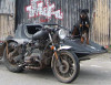
Mitsubishi Outlander Rear Motor
BMW K100 Gearbox and final drive +rear wheel
BMW i3 battery modules
Toyota Gen3 Inverter also working as charger
Custom built aluminium frame
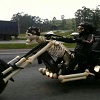
I know this is going to be a real heavy weight but as my current ride is a VW 1900cc TDi motorcycle with car gearbox weighing in at just under 400kg I know what I'm letting myself in for.
The main technical stalling point for a long time was motor reduction for driving the prop shaft to he rear wheel. The original idea was to have a dedicated 2:1 reduction to the bike prop shaft and avoid having the original gearbox But I was unsuccessful finding anyone who would make me a hardened shaft. So after much deliberation I decided to use the original bike gearbox and just leave it in the appropriate gear all the time. The only disadvantage is that this adds about 6" to an already long vehicle. The major upshot is all the specialist parts like splines are off the shelf items making it very cost effective over having a hard to replace custom part made and hardened.
The coupling between the motor and gearbox is the first part made for the project. Made from a BMW bike clutch plate and a Suzuki Jimny clutch plate bolted together with a aluminium spacer. All fabricated in the garden shed workshop. Total cost about £50-£60 especially as the BMW clutch plate was obtained from a dealer who sold me one with worn out friction plates out of the bin and the slug of ally was an off-cut I spotted in the local scrapyard ally bin.
Motor clutch plate Part No
BLUEPRINT ADK83106
https://www.ebay.co.uk/itm/264257628857 This link will probably go stale at some point
It's more effective than you'd think
I'll probably make up a spindle to go through both splines to make sure they are absolutely concentric before bolting up permanently.
The next construction job is to make bracketry to mount the gearbox on the motor and get both splines concentric. Then this will be considered a single unit to build the chassis and battery box around. I've done this sort shaft coupling alignment with previous diesel powered motorbike projects where I've fitted small diesel engines to the BMW motorbike gearboxes giving me a head start when planning such a thing.