Great work,
nice to see a few more pins have been found i was suspecting a digital pins used, as i been trying to follow the hybrid pack eval board design. which they seemed to have barrowed there ideas from
i haven't tested to much lately as my garage has been below freezing and awaiting for the connector i ordered to see if its correct
i think i tracked back pin 14 to be hv dc bus measurement voltage but not had a chance to confirm it yet.
i3 controller hacking from diyelectriccar.com
-
golfdubcrazy
- Posts: 85
- Joined: Thu Jan 28, 2021 6:15 pm
- Has thanked: 1 time
- Been thanked: 11 times
-
johu

- Site Admin
- Posts: 6769
- Joined: Thu Nov 08, 2018 10:52 pm
- Location: Kassel/Germany
- Has thanked: 383 times
- Been thanked: 1589 times
- Contact:
Re: i3 controller hacking from diyelectriccar.com
Tested SPI comms today. So like said, the protocol is pretty easy.
ADC is run in manual mode, i.e. no automatic channel sequencing. To select that, 4096 is sent via 16 bit SPI transfer. To read channel 5 (DC link voltage) we also have to set bits 9 and 7, so we send 4096+512+128=4736. The ADC then returns 5 << 12 (the channel number) and the 12-bit conversion result. So we just use a 0xFFF mask to get rid of the channel number and we have our result. Below you see me sweeping from 10 to 30V. 10V is represented as 160 digits.
Getting the physical comms to work was slightly more difficult. SPI needs to run at at fairly low speed. I chose the highest prescaler of 256 which results in 140 kHz clock speed. I already got bogus results when running at 560 kHz. Also /CS can't just be pulled low constantly but you have to pull it low, do your transfer, take it high again. Otherwise there is no response.
In code it looks like this:
Code: Select all
spi_init_master(SPI2, SPI_CR1_BAUDRATE_FPCLK_DIV_256, SPI_CR1_CPOL_CLK_TO_0_WHEN_IDLE,
                  SPI_CR1_CPHA_CLK_TRANSITION_2, SPI_CR1_DFF_8BIT, SPI_CR1_MSBFIRST);

   spi_enable_software_slave_management(SPI2);
   spi_set_dff_16bit(SPI2);
   spi_set_nss_high(SPI2);
   gpio_set_mode(GPIOB, GPIO_MODE_OUTPUT_50_MHZ,
            GPIO_CNF_OUTPUT_ALTFN_PUSHPULL, GPIO13 | GPIO15 );
   spi_enable(SPI2);

   //in some task:
   Param::SetInt(Param::udc, spi_xfer(SPI2, 4736)) & 0xFFF);
- Attachments
-
Support R/D and forum on Patreon: https://patreon.com/openinverter - Subscribe on odysee: https://odysee.com/@openinverter:9
-
johu
- Site Admin
- Posts: 6769
- Joined: Thu Nov 08, 2018 10:52 pm
- Location: Kassel/Germany
- Has thanked: 383 times
- Been thanked: 1589 times
- Contact:
Re: i3 controller hacking from diyelectriccar.com
I would be surprised, as bus voltage is definitely on that ADC. I think there is a second SPI bus going to the mystery chip. It has /CS constantly low. I thought bus discharge but doesn't really add up. Where is that eval board design you mentioned?golfdubcrazy wrote: ↑Sun Feb 14, 2021 10:08 pm i think i tracked back pin 14 to be hv dc bus measurement voltage but not had a chance to confirm it yet.
Support R/D and forum on Patreon: https://patreon.com/openinverter - Subscribe on odysee: https://odysee.com/@openinverter:9
-
johu
- Site Admin
- Posts: 6769
- Joined: Thu Nov 08, 2018 10:52 pm
- Location: Kassel/Germany
- Has thanked: 383 times
- Been thanked: 1589 times
- Contact:
Re: i3 controller hacking from diyelectriccar.com
Also had a look around for 32V boost regulators that can source like 0.5A of current. The little SOIC or SOT-23-6 jobbies don't really seem to be up to it. They might specify 1.5A switching current but then in the app note it says 32V, 175 mA.
So I thought we might need something more serious, like the TPS61175. Available on JLC and it has the notorious ground pad.
Other alternative is a more generic regulator with external transistor.
Layout-wise I would make the board roughly 15x10cm. It would be bolted on 3 points and extend to the ribbon cable from the driver board. Would also make cutouts to make it easier to access the phase terminals. Need to look at the enclosure a bit, the external connector will most probably be ampseal attached via ribbon, like on Damiens Prius board.
Is the DC-DC and charger module hacked yet? Would be nice to actually use the entire device not just the inverter.
Support R/D and forum on Patreon: https://patreon.com/openinverter - Subscribe on odysee: https://odysee.com/@openinverter:9
-
johu
- Site Admin
- Posts: 6769
- Joined: Thu Nov 08, 2018 10:52 pm
- Location: Kassel/Germany
- Has thanked: 383 times
- Been thanked: 1589 times
- Contact:
Re: i3 controller hacking from diyelectriccar.com
And this should be the correct header: https://www.digikey.de/product-detail/d ... ND/8537679
I think it can only be reflowed as the first pin row is obscured by the second.
The straight version could be hand-soldered, just have to check of the ribbon is long enough
I think it can only be reflowed as the first pin row is obscured by the second.
The straight version could be hand-soldered, just have to check of the ribbon is long enough
Support R/D and forum on Patreon: https://patreon.com/openinverter - Subscribe on odysee: https://odysee.com/@openinverter:9
-
golfdubcrazy
- Posts: 85
- Joined: Thu Jan 28, 2021 6:15 pm
- Has thanked: 1 time
- Been thanked: 11 times
Re: i3 controller hacking from diyelectriccar.com
Great work Johu 
Yes that is the correct header mine arrived today and fits beautifully.
Infineon made an evaluation module for Hybrid pack. i have been comparing the schematics from there datasheet to this module. there are a few differences but helped narrow things down. links below
https://www.infineon.com/cms/en/product ... kit-drive/
https://www.mouser.se/datasheet/2/196/I ... 317687.pdf
- Attachments
-
-
-
Hans Gustafsson
- Posts: 20
- Joined: Tue Feb 09, 2021 9:13 am
- Location: Sweden
- Been thanked: 1 time
Re: i3 controller hacking from diyelectriccar.com
Some thoughts from a potential board buyer:
The BMW motor is 12 pole and has a maximum speed of 11400Rev / min. My Bamocar D3 400-400 inverter does not allow too low PWM frequency at higher speeds, when I do an "auto setup". It has a variable PWM frequency depending on the speed and reduces the permitted current at the higher frequencies. In my conversion, I also have BMW's singel speed gearbox and have to use the higher speeds. A 3000km Gearbox + engine 1000EUR. The drive shafts were 800EUR and only needed to shorten one shaft a bit and they fit in Renault's outer CV joints. Have tested the drive package in the car, but an IGBT broke down. Got the correct error code anyway, after checking the IGBT's. I also have a maximum of 440 volts on my battery pack and hope BMW's inverter can take it. As an old car designer, I know that the easiest way to sell a car is with horsepower. That probably applies to your boards as well.
The BMW motor is 12 pole and has a maximum speed of 11400Rev / min. My Bamocar D3 400-400 inverter does not allow too low PWM frequency at higher speeds, when I do an "auto setup". It has a variable PWM frequency depending on the speed and reduces the permitted current at the higher frequencies. In my conversion, I also have BMW's singel speed gearbox and have to use the higher speeds. A 3000km Gearbox + engine 1000EUR. The drive shafts were 800EUR and only needed to shorten one shaft a bit and they fit in Renault's outer CV joints. Have tested the drive package in the car, but an IGBT broke down. Got the correct error code anyway, after checking the IGBT's. I also have a maximum of 440 volts on my battery pack and hope BMW's inverter can take it. As an old car designer, I know that the easiest way to sell a car is with horsepower. That probably applies to your boards as well.

Re: i3 controller hacking from diyelectriccar.com
Good job Guy's !
I'm also working on this inverter but I took a different way, I used the original LEM current sensor, get rid of the board and use the gate driver from Johu, might not be the best thing to do, but I tough it would be easier for me... no need to reverse engineer this board and less time consuming, I will keep reading your updates
BMW I3 Project
viewtopic.php?f=11&t=736&sid=002463d39c ... 3ad7740f1f
Sorry if some sentences make non sense... I'm French!
-
johu
- Site Admin
- Posts: 6769
- Joined: Thu Nov 08, 2018 10:52 pm
- Location: Kassel/Germany
- Has thanked: 383 times
- Been thanked: 1589 times
- Contact:
Re: i3 controller hacking from diyelectriccar.com
Yes that will also work but of course the OEM drivers offer some more protection. They can also be connected to the PWM outputs as is, the only challenge is the 32V supply voltage.
Only temp and bus voltage measurement are more difficult to interface but you can just use the voltage sense board included with the kit to overcome that.
Only temp and bus voltage measurement are more difficult to interface but you can just use the voltage sense board included with the kit to overcome that.
Support R/D and forum on Patreon: https://patreon.com/openinverter - Subscribe on odysee: https://odysee.com/@openinverter:9
-
Jack Bauer

- Posts: 3667
- Joined: Wed Dec 12, 2018 5:24 pm
- Location: Ireland
- Has thanked: 12 times
- Been thanked: 354 times
- Contact:
Re: i3 controller hacking from diyelectriccar.com
For the 32v supply you could use the same mc34063 circuit I use on the prius gen 3 boards. Good to 1.5amps. just change the feedback resistors to give 32v instead of 26v.
I'm going to need a hacksaw
-
johu
- Site Admin
- Posts: 6769
- Joined: Thu Nov 08, 2018 10:52 pm
- Location: Kassel/Germany
- Has thanked: 383 times
- Been thanked: 1589 times
- Contact:
Re: i3 controller hacking from diyelectriccar.com
Yes thats one of the boosters that state only 175mA output in the data sheet. even though I'm not sure why, 12 to 32V@350mA should mean about 1A of inductor current, right?
Support R/D and forum on Patreon: https://patreon.com/openinverter - Subscribe on odysee: https://odysee.com/@openinverter:9
-
Hans Gustafsson
- Posts: 20
- Joined: Tue Feb 09, 2021 9:13 am
- Location: Sweden
- Been thanked: 1 time
Re: i3 controller hacking from diyelectriccar.com
Here are some steps up 13.8v to 32v between 2-8 amp options.
https://www.aliexpress.com/item/1000007 ... web201603_
https://www.aliexpress.com/item/1000007 ... web201603_
-
golfdubcrazy
- Posts: 85
- Joined: Thu Jan 28, 2021 6:15 pm
- Has thanked: 1 time
- Been thanked: 11 times
Re: i3 controller hacking from diyelectriccar.com
Hi All,
sorry slow progress as back to work. been looking online and wonder is this buck booster would be a nice enough circuit for the 32v supply.
https://www.ebay.co.uk/itm/DC-DC-4A-Boo ... SwJ7RYSpuR
thinking of purchasing one for testing.
sorry slow progress as back to work. been looking online and wonder is this buck booster would be a nice enough circuit for the 32v supply.
https://www.ebay.co.uk/itm/DC-DC-4A-Boo ... SwJ7RYSpuR
thinking of purchasing one for testing.
-
johu
- Site Admin
- Posts: 6769
- Joined: Thu Nov 08, 2018 10:52 pm
- Location: Kassel/Germany
- Has thanked: 383 times
- Been thanked: 1589 times
- Contact:
Re: i3 controller hacking from diyelectriccar.com
First cut done 
Will send it out to almighty JLC tomorrow probably.
I use a 23-pin ampseal with reduced IO-set that is assigned similar to the B-class (SDU) ampseal
Will send it out to almighty JLC tomorrow probably.
I use a 23-pin ampseal with reduced IO-set that is assigned similar to the B-class (SDU) ampseal
- Attachments
-
Support R/D and forum on Patreon: https://patreon.com/openinverter - Subscribe on odysee: https://odysee.com/@openinverter:9
Re: i3 controller hacking from diyelectriccar.com
Nice job!!!
The stm32 (brain) will be inside the inverter via the (2) SIL headers?
The stm32 (brain) will be inside the inverter via the (2) SIL headers?
Sorry if some sentences make non sense... I'm French!
-
golfdubcrazy
- Posts: 85
- Joined: Thu Jan 28, 2021 6:15 pm
- Has thanked: 1 time
- Been thanked: 11 times
Re: i3 controller hacking from diyelectriccar.com
Amazing work let us know when one is ready for purchase
also can you add a VW section into hardware i have a VW GTE battery pack that i can show dissembled
also can you add a VW section into hardware i have a VW GTE battery pack that i can show dissembled
-
johu
- Site Admin
- Posts: 6769
- Joined: Thu Nov 08, 2018 10:52 pm
- Location: Kassel/Germany
- Has thanked: 383 times
- Been thanked: 1589 times
- Contact:
Re: i3 controller hacking from diyelectriccar.com
Thanks
Wait, how can I not have a VW section yet? Of course, will do.golfdubcrazy wrote: ↑Sat Mar 13, 2021 5:24 pm Amazing work let us know when one is ready for purchase
also can you add a VW section into hardware i have a VW GTE battery pack that i can show dissembled
Support R/D and forum on Patreon: https://patreon.com/openinverter - Subscribe on odysee: https://odysee.com/@openinverter:9
-
arber333
- Posts: 3578
- Joined: Mon Dec 24, 2018 1:37 pm
- Location: Slovenia
- Has thanked: 134 times
- Been thanked: 342 times
- Contact:
Re: i3 controller hacking from diyelectriccar.com
You could also transfer that thread there
viewtopic.php?p=7953#p7953
I have a GTE charger, GTE inverter and GTE battery modules waiting...
Re: i3 controller hacking from diyelectriccar.com
Are you sure... see my picture in the other tread https://openinverter.org/forum/downloa ... mode=view , the gate driver connector on the left (white tape and yellow paint) is almost touching the cover, for that reason I use the yellow paint to be sure the wire will not rub against the inverter cover, I was not able to put the brain on top of the gate driver (not enough space)Thanks
Sorry if some sentences make non sense... I'm French!
-
johu
- Site Admin
- Posts: 6769
- Joined: Thu Nov 08, 2018 10:52 pm
- Location: Kassel/Germany
- Has thanked: 383 times
- Been thanked: 1589 times
- Contact:
Re: i3 controller hacking from diyelectriccar.com
I see what you mean, the enclosure slopes downwards towards the edge.
I have a handicap here, I don't have the enclosure
I have a handicap here, I don't have the enclosure
- Attachments
-
Support R/D and forum on Patreon: https://patreon.com/openinverter - Subscribe on odysee: https://odysee.com/@openinverter:9
-
johu
- Site Admin
- Posts: 6769
- Joined: Thu Nov 08, 2018 10:52 pm
- Location: Kassel/Germany
- Has thanked: 383 times
- Been thanked: 1589 times
- Contact:
Re: i3 controller hacking from diyelectriccar.com
Mail from JLCPCB today
The board "in general" is working but has a few design flaws.
The board "in general" is working but has a few design flaws.
- The 32V boost converter overheats and cuts back seconds after the PWM becomes active. It will need more cooling and lower switching frequency. 1 Mhz is too much. That also means larger inductor.
- The communication between ESP and STM is disturbed and I cannot refresh the parameters once the PWM is running. Will need better routing and perhaps some low pass filtering.
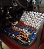
- SPI is not working because there is a voltage divider before the digital isolator. WTF? Anyway, seems my test board with LD1117 had like 0.07V higher 3V3 level and just made it, the mini mainboard with just 3.27V doesn't make it. Will need to add a buffer. On the pic you see one from my 74 collection.
- Attachments
-
Support R/D and forum on Patreon: https://patreon.com/openinverter - Subscribe on odysee: https://odysee.com/@openinverter:9
Re: i3 controller hacking from diyelectriccar.com
I could potentially test in Finland. I have access to a complete unit. It's not mine but I'll check if it's OK to open it.
I think I'll buy it anyway after this project is complete
I think I'll buy it anyway after this project is complete
-
golfdubcrazy
- Posts: 85
- Joined: Thu Jan 28, 2021 6:15 pm
- Has thanked: 1 time
- Been thanked: 11 times
Re: i3 controller hacking from diyelectriccar.com
i have the complete inverter, can give it a test fit if heikki cant im in the UK if that's any easier for you.
-
johu
- Site Admin
- Posts: 6769
- Joined: Thu Nov 08, 2018 10:52 pm
- Location: Kassel/Germany
- Has thanked: 383 times
- Been thanked: 1589 times
- Contact:
Re: i3 controller hacking from diyelectriccar.com
Will send one to Heikki, can you send me your address? Sorry, UK has become harder to ship to since Brexit.
Did some more testing and finally found that right way too talk to the ADC. The reference needs to be set to 2xVref which means bit 6 must be set in the request. But for bit 6 to have an effect, bit 11 must also be set
So the final request: 4096 + 2048 + 64 + (channel << 7). So to sample channel 3 send 6592. I also found that channel 3 is also connected to bus voltage.
Support R/D and forum on Patreon: https://patreon.com/openinverter - Subscribe on odysee: https://odysee.com/@openinverter:9