'13 CRF250L motorcycle

Tell us about the project you do with the open inverter
User avatar
mjc506
Posts: 343
Joined: Wed Sep 09, 2020 9:36 pm
Location: Wales, United Kingdom
Has thanked: 30 times
Been thanked: 28 times

'13 CRF250L motorcycle

Post by mjc506 »

'ning All.

This will probably be a slow one, but may as well get started!

I have a 2013 Honda CRF250L m/c. It's running and road legal, but is starting to show issues with the ICE, including reduction in compression, slight leaks on valve seals, and wear on the countershaft splines - it'd need top end off and cases splitting to sort these things out. That said, that's mostly an excuse to convert to electric :)

Legalities for a motorcycle seem easier than a car here in the UK, so long as the frame isn't altered (easy enough, make everything bolt to engine mounts and/or existing bolt holes etc, or with clamps around frame tubes). Should just need to advise insurance, take an MoT, and return the V5 to get the fuel type changed. We'll see though...

Finding suitable conversion parts has been difficult. Very little second hand/salvage electric motorcycle parts around! And of course using car parts and de-rating results in excessive weight. New motor/controller kits are of course available, but the costs (and now, import hassles) make these difficult to justify.

The bike weighs approx. 145kg in its current form, and removing all the ICE parts saves approx. 58kg. I'd like the converted machine to be no heavier than stock. Absolute minimum is 25miles range, in hilly Wales (this is my commute) but more is of course better... I've recorded my commute, done some coasting tests etc, and calculated my CdA and rolling resistance reasonably accurately, so I also know my kW and kWh targets - 5kw gives me 57mph (a perfectly adequate cruise on this machine and these roads), and 2.8kWh capacity is absolute minimum (this accounts for decent SoC de-ratings). Voltage and gearing are as yet unknown, as they largely depend on the kV of the motor.

While searching for a suitable inverter and motor, I started looking at mild hybrid starter-generators - many recent models are pancake motors which would be difficult to package (plus lack bearings, full housing etc), but 'milder'/smaller/older hybrids are more often belt-driven - this would be ideal for a bike as they're a 'better' shape for the frame, have good bearings (belt loads are quite high) and generally include good mounts. They tend to be expensive though, but this led me on to a standard car alternator - essentially a poly-phase generator with a rectifier. These are easy to convert into a motor (cut off the rectifier, solder new wires to the connections), also have good bearings and mountings, and survive many years in a hostile environment so are rugged. The downside is that they generally require the rotor to be excited - they have two brushes and slip rings; however, as it's DC and slip rings (not a commutator) and low currents, these last ages, and don't use masses of power (a couple of watts generally). Also, the current can be varied to adjust the kV of the motor! (high current at low speeds to increase torque, lower current as speed increases to increase rpm) I believe I can treat these motor as a PMSM... and don't have to worry about cooking magnets...

As for the inverter, I've got hold of a gen1 Honda Civic IMA inverter - these seem simple to drive, and compact. I've read reports of >17kW from these. Later generations seem to be more compact (gen1 has separate HV capacitors, gen2 has the capacitor potted into the inverter case, for example).
Image
(already removed most of the bolts before remembering photos...)
Some lovely plated copper bus bars for DC and phases. 3 400V 470uF capacitors, plus some smaller film caps for DC filtering. Current sensors on each phase and DC in. (Under the metal lid in the photo is a DC-DC converter - these have been tested to <70A, and run from 60 to 220V on the HV side.

Inside the inverter are 6 Mitsubishi IGBT drivers, and a Motorola uC... not entirely sure what it does, perhaps some protection functions.
Image
It takes the HV bus on the two terminals at the bottom, but aside from that, there's a 12V and Gnd, one mystery output (an error signal perhaps?) and 6 inputs label UL, UH, VL, VH, WL and WH. No prizes for guessing what they are :) The current sensors and encoder are read by an external 'MCM' unit, which an openinverter board (on its way!) will replace :) I haven't removed the pcb from the case - I think that doing so would be destructive, and there seems no real need at the moment.

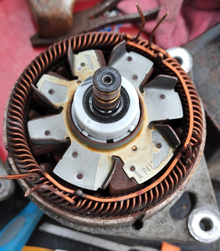
I also have a car alternator to sacrifice/convert - a 150amp unit from a Fiesta. This was perhaps overkill - it actually has 6(!) phases - smaller alternators are more likely to be three phase. Still, it'll be good to test with at least, and I can either treat it as a 75amp motor with a spare set of phases :) or I might try tieing together the pairs of phases to get one set of 'wide' phases - no way this would work sensorless, but perhaps with the resolver I'm planning to use, and a bit of luck, it'll work reasonably well...

Next task is to fix everything to a suitable board for testing, and await arrival of the openinverter board and wire it up! I'll be testing at low voltages first (a couple car batteries will do for now I think). I'll be able to work out a relationship between stall torque and rotor current, and also no load rpm at varying HV voltage and rotor current. That should give me an idea of kV range, and gearing and voltages required.
User avatar
clanger9
Posts: 203
Joined: Mon Oct 28, 2019 7:41 am
Location: Chester, UK
Been thanked: 1 time
Contact:

Re: '13 CRF250L motorcycle

Post by clanger9 »

Nice project!

Have you had a look at hub motors? I don't know whether they are any good, but something like this might work well in a small bike:
https://www.amazon.co.uk/NBPOWER-Electr ... B07Z98YYP3
User avatar
johu
Site Admin
Posts: 5791
Joined: Thu Nov 08, 2018 10:52 pm
Location: Kassel/Germany
Has thanked: 157 times
Been thanked: 1023 times
Contact:

Re: '13 CRF250L motorcycle

Post by johu »

Always wanted to know how capable alternators are so following with interest :)
If you can't fit a resolver maybe this helps: viewtopic.php?f=14&t=1225&hilit=sin+cos&start=50
Support R/D and forum on Patreon: https://patreon.com/openinverter - Subscribe on odysee: https://odysee.com/@openinverter:9
User avatar
mjc506
Posts: 343
Joined: Wed Sep 09, 2020 9:36 pm
Location: Wales, United Kingdom
Has thanked: 30 times
Been thanked: 28 times

Re: '13 CRF250L motorcycle

Post by mjc506 »

clanger9 wrote: Tue Feb 02, 2021 10:28 pm Nice project!

Have you had a look at hub motors? I don't know whether they are any good, but something like this might work well in a small bike:
https://www.amazon.co.uk/NBPOWER-Electr ... B07Z98YYP3
Thanks :) Yes, hub motors would be easier (and give more room for batteries in the frame) but I'm perhaps needlessly concerned about low speed/stalled torque, and also unsprung weight (this is a 'dual sport' m/c, and I'll still be riding it off tarmac)
johu wrote: Tue Feb 02, 2021 10:32 pm Always wanted to know how capable alternators are so following with interest :)
If you can't fit a resolver maybe this helps: viewtopic.php?f=14&t=1225&hilit=sin+cos&start=50
It'll be an interesting experiment! It only cost me £15.00 delivered to my door, so £/kW should be quite good haha. Thanks, yes, I saw that thread. I intend to use an MLX91204 to give sin/cos output, I think this will give the best data for the openinverter board.
User avatar
johu
Site Admin
Posts: 5791
Joined: Thu Nov 08, 2018 10:52 pm
Location: Kassel/Germany
Has thanked: 157 times
Been thanked: 1023 times
Contact:

Re: '13 CRF250L motorcycle

Post by johu »

Yes used exactly that in the past, it works great when powered by the same 3v3 as the processor.
Support R/D and forum on Patreon: https://patreon.com/openinverter - Subscribe on odysee: https://odysee.com/@openinverter:9
User avatar
mjc506
Posts: 343
Joined: Wed Sep 09, 2020 9:36 pm
Location: Wales, United Kingdom
Has thanked: 30 times
Been thanked: 28 times

Re: '13 CRF250L motorcycle

Post by mjc506 »

Excellent, a good chance of at least one thing working well then :lol:
User avatar
clanger9
Posts: 203
Joined: Mon Oct 28, 2019 7:41 am
Location: Chester, UK
Been thanked: 1 time
Contact:

Re: '13 CRF250L motorcycle

Post by clanger9 »

mjc506 wrote: Tue Feb 02, 2021 10:38 pm
clanger9 wrote: Tue Feb 02, 2021 10:28 pm Have you had a look at hub motors? I don't know whether they are any good, but something like this might work well in a small bike:
https://www.amazon.co.uk/NBPOWER-Electr ... B07Z98YYP3
Yes, hub motors would be easier (and give more room for batteries in the frame) but I'm perhaps needlessly concerned about low speed/stalled torque, and also unsprung weight (this is a 'dual sport' m/c, and I'll still be riding it off tarmac)
Yes, I'm with you there. I'd like to ride a bike with one to see what they're like, but chain or belt drive seems to be the way to go. Hub motors are *heavy* as well...
User avatar
Bratitude
Posts: 784
Joined: Thu Jan 02, 2020 7:35 pm
Location: Canada
Has thanked: 58 times
Been thanked: 176 times
Contact:

Re: '13 CRF250L motorcycle

Post by Bratitude »

Did you come across the sonata hsg in your search for a motor? It’s essentially a alternator with the hv 3phase connections and a liquid cooling jacket
https://bratindustries.net/ leaf motor couplers, adapter plates, custom drive train components
User avatar
mjc506
Posts: 343
Joined: Wed Sep 09, 2020 9:36 pm
Location: Wales, United Kingdom
Has thanked: 30 times
Been thanked: 28 times

Re: '13 CRF250L motorcycle

Post by mjc506 »

Yes, the Hyundai BSGs are an interesting unit - 3 phase motor, water cooled, some form of encoder built in... would be a good option, but they're pricey over here even salvage. Some of the 48v mild hybrid BMWs even have a BSG with internal inverter (ie, no good for us, but if drivable over CAN, would make it really simple!)
User avatar
mjc506
Posts: 343
Joined: Wed Sep 09, 2020 9:36 pm
Location: Wales, United Kingdom
Has thanked: 30 times
Been thanked: 28 times

Re: '13 CRF250L motorcycle

Post by mjc506 »

Playing a bit more with the alternator today.

Image

Seems to be 6 phase, Wye connection. I'll separate the phases to give me 12 wires which I can play around with externally, but will probably end up connecting in delta. Funky asymmetrical fan too, weird. I guess this is something to do with balancing, but won't mess with it too much.

Something else to look out for if doing alternator conversions - this one, and many recent models I suspect, has an overrunning pulley. This of course either means no drive, or no regen! It looks like I could get a solid pulley for this one, but it may be more cost effective to get a complete alternator with solid pulley (perhaps from a referb company) for when I convert the bike. Or, just creatively break the clutch so it's fixed, but that may turn into one of those 'permanently temporary' bodges...
User avatar
mjc506
Posts: 343
Joined: Wed Sep 09, 2020 9:36 pm
Location: Wales, United Kingdom
Has thanked: 30 times
Been thanked: 28 times

Re: '13 CRF250L motorcycle

Post by mjc506 »

A little more progress over the weekend...

Attached everything to a sheet of ply to keep things together, and to stop the motor taking off if/when it started spinning :) I'm using an old car battery for both 12V and 'HV' at the moment, but have something better on the way.

First things first, powered up the openinverter board, which of course works perfectly :)

Next, powering up the inverter. Two ground lines and two power, which are tied together inside the inverter. I suspected it required 12V, but couldn't confirm this on the schematic, so connected to an adjustable CV regulator, and slowly increased the voltage. At ~4.5V it woke up, and started making encouraging noises, but checking voltages on the switch mode 15V supply inside (for the IGBTs) showed they were low. Increasing the voltage changed the tone of the switch mode whine, and by 12V had gone ultrasonic and voltages were a healthy 15V in the right places.

Aside from the power connections, the inverter unit has 7 other wires on its plug. 6 of them are U, V, W high and low, but the 7th is a bit of a mystery. There's no real point having an 'enable' line when you can just stop pwming the UVW lines, so I assume it may be an 'error' output. The schematic labelled the U_high line as blue with a black stripe, and I found the matching wire. Connecting it to 3V had no effect (I was checking the IGBT pins for any changes, and hoping for a nice +15V somewhere), so I tried 5V, and then 12V. Nothing. I spent a good few hours trying to find out why it wasn't working, only to realise that Mr Honda had decided that it'd be a good idea to have two wires of the same colour in one harness... Gah! Now using the correct wire, inputting 3V resulted in a good +15V on one of the IGBT pins. Huzzah! This means the main board can drive this inverter directly without any other requirements.

Current sensors were easy (there's one on each phase, and also one on DC in) although I still need to calibrate them.

I was still curious about that 7th wire. The multimeter said ~2.5V, so I plugged in a logic analyser. It's a serial line! I still need to decode it, but I suspect it'll at least give HV voltage, hopefully temperature(s) too, and maybe error signals. If I can read those, and the DC current sensor, with a small 'duino or similar, I should be able to spit the data over CAN for the openinverter board to use. Or perhaps, as I'll now have a few inputs spare, I can play with the code and read directly - I intend to make a few changes at some point anyway to suit the motorcycle layout and hardware.

Next steps are to get the motor spinning (open loop, the sincos encoder hasn't arrived yet) and perhaps play with the DC-DC.
User avatar
johu
Site Admin
Posts: 5791
Joined: Thu Nov 08, 2018 10:52 pm
Location: Kassel/Germany
Has thanked: 157 times
Been thanked: 1023 times
Contact:

Re: '13 CRF250L motorcycle

Post by johu »

Nice progress. Thought about rotor excitation. You could use the user PWM feature (brought out via the ULN2003 chip) to generate a duty cycle dependent on speed. Frequency is fixed to 17.6 kHz though.
Support R/D and forum on Patreon: https://patreon.com/openinverter - Subscribe on odysee: https://odysee.com/@openinverter:9
User avatar
mjc506
Posts: 343
Joined: Wed Sep 09, 2020 9:36 pm
Location: Wales, United Kingdom
Has thanked: 30 times
Been thanked: 28 times

Re: '13 CRF250L motorcycle

Post by mjc506 »

Certainly a possibility :-) frequency shouldn't be an issue, would probably have to invert the signal to get higher currents at lower speeds, but it'll need at least a mosfet anyway. I'm not sure what the 'optimum' current/speed relationship looks like, it may not be critical.
User avatar
mjc506
Posts: 343
Joined: Wed Sep 09, 2020 9:36 pm
Location: Wales, United Kingdom
Has thanked: 30 times
Been thanked: 28 times

Re: '13 CRF250L motorcycle

Post by mjc506 »

Got the DC-DC working. Far too easy. All it needs is HV (>55V, <220V), 12V on its output, and one line (black with orange stripe) pulled high. If HV is too low or too high it'll shut down, as will dropping black/orange, but comes back as soon as HV returns in range (no reset etc required). Strong 13.8V output. I've seen reports of ~1kW, and seems to have internal temp shutdown. Lots of other pins on its connector, suspect this may include a PWM to adjust the voltage, and some output (perhaps serial, like the inverter).

Hopefully get some more play time tomorrow... :)

Edit: in fact, it'll accept anything higher than ~4.5V on its '12V' output and black/orange to start up!
User avatar
mjc506
Posts: 343
Joined: Wed Sep 09, 2020 9:36 pm
Location: Wales, United Kingdom
Has thanked: 30 times
Been thanked: 28 times

Re: '13 CRF250L motorcycle

Post by mjc506 »

I've been looking at the serial output from the Honda inverter unit.

Using the logic analyser, I've narrowed it down to 10400 baud, 8 bytes, equal parity, 1 stop bit. There are 5 packets being sent out in a loop, each made up of a ID byte (either 0xE1, E6, F8, D2 or D5), four bytes of data and a checksum byte. The first data byte (after the ID) of each 'word' is the same, and changes with HV voltage.

HV voltage correlates pretty well with 2*byte1+10, so I can read this with a 'duino and send it out over CAN to the openinverter board. Apart from this, everything else seems fairly static, aside from small changes over time on the 0xD2 word - the 2nd, 3rd and 4th data bytes seem to increase slowly from powerup, and appear to correlate reasonably well with temperature. I need to check with a heat gun and thermometer (difficult to read the temp of an aluminium heatsink with an IR thermometer), but I might have heatsink and board temperatures (in half degrees Celius), plus the 4th byte which I can't work out yet. I assume there's gonna be error bits in there too, but without the rest of the Honda electronics etc I'm unlikely to be able to decode them. Never mind, voltage and temps are the most useful.

Also confirmed that the openinverter board can happily drive the Honda inverter/IGBTs, I get a nice output from the IGBTs (with ~1us of deadtime?). I tried spinning the motor but was unsuccessful. At one point I had the inverter trying to get it going, but there was no movement and just a quiet clunking from the motor. All attempts after that just had the inverter shut down within half a second reporting 'overcurrent' so I need to track down the cause of that. Problems could be down to any number of things - wrong field current, crappy psu, crappy 12V, insufficient deadtime(?), and of course the motor itself... I'll attempt with some bulbs next time.

One question; I'm currently following the wiki which says to use the 'sine' firmware for testing. I should still get some movement using this even with a PMSM do you think?
User avatar
johu
Site Admin
Posts: 5791
Joined: Thu Nov 08, 2018 10:52 pm
Location: Kassel/Germany
Has thanked: 157 times
Been thanked: 1023 times
Contact:

Re: '13 CRF250L motorcycle

Post by johu »

mjc506 wrote: Tue Feb 09, 2021 9:46 pm One question; I'm currently following the wiki which says to use the 'sine' firmware for testing. I should still get some movement using this even with a PMSM do you think?
Yes, down in the low frequency (like 5Hz) region it is possible to spin it open loop. With some patience you might be able to spin faster but there is no real point to that.
Support R/D and forum on Patreon: https://patreon.com/openinverter - Subscribe on odysee: https://odysee.com/@openinverter:9
User avatar
mjc506
Posts: 343
Joined: Wed Sep 09, 2020 9:36 pm
Location: Wales, United Kingdom
Has thanked: 30 times
Been thanked: 28 times

Re: '13 CRF250L motorcycle

Post by mjc506 »

Thanks, so I should be ok just to get it spinning whilst testing. But perhaps best to move to foc firmware now I know the inverter itself is fine. Still waiting for the sin/cos encoder :(
User avatar
mjc506
Posts: 343
Joined: Wed Sep 09, 2020 9:36 pm
Location: Wales, United Kingdom
Has thanked: 30 times
Been thanked: 28 times

Re: '13 CRF250L motorcycle

Post by mjc506 »

Success!

Many thanks to Johannes for his patience with my ineptitude on other posts...

During the week, I got hold of another alternator - this one's a 100A Bosch unit from a Corsa (many Vauxhall/Opel cars seem to take similar alternators) with a solid pulley (no one-way clutch), and three phases on the stator windings - these are accessible from the rear of the alternator just by removing the diode pack as 6 connections, so it'd be possible to connect in delta or wye. The regulator can be butchered slightly to get to the brush connections.

I wrote some basic software for an Arduino to read the serial line from the inverter and send udc and temperatures over CAN to the mainboard. I'll need to get it reading the dc bus current sensor too at some point (the mainboard firmware calculates idc, but I think it'd be nicer to measure it directly). Getting the mainboard to read udc from CAN needed some small edits to the firmware, as will idc and temperatures. But udc at least is now working nicely.

I connected the HV bus to a 12V car battery (through a 100A fuse), and connected the alternator to U,V,W in delta, and a CC power supply to the brushes set at 0.5A. Started the inverter in 'manual mode' at 10Hz, and it spins! I also discovered that it'll spin (and start up) with the brushes disconnected, although noticeably less torque as expected. This could be helpful when getting into field weakening speeds - with no field current, tripping a contactor may not be catastrophic... On the other hand, this may this be indicating that the rotor has been magnetised, I can check by spinning the rotor by hand and checking voltage across the phases.

Next steps are to get a magnet fixed to the shaft and the sin/cos encoder wired up and mounted, and get the FOC firmware running. Also need to get some switches and potentiometers set up as bench test controls, and then I can start working out kV and kI for the motor/alternator at various field currents, which will let me work out what sort of gearing and pack voltage I'll need. And start replacing the cheap crocodile clips and thin melty cables with something a bit thicker... :)
User avatar
johu
Site Admin
Posts: 5791
Joined: Thu Nov 08, 2018 10:52 pm
Location: Kassel/Germany
Has thanked: 157 times
Been thanked: 1023 times
Contact:

Re: '13 CRF250L motorcycle

Post by johu »

Nice progress! Maybe you can even turn it into an asynchronous motor by shorting rotor windings :) Just joking, I think it would be very inefficient.
Support R/D and forum on Patreon: https://patreon.com/openinverter - Subscribe on odysee: https://odysee.com/@openinverter:9
User avatar
mjc506
Posts: 343
Joined: Wed Sep 09, 2020 9:36 pm
Location: Wales, United Kingdom
Has thanked: 30 times
Been thanked: 28 times

Re: '13 CRF250L motorcycle

Post by mjc506 »

Thanks :)

Haha yes, it could be a good battery heating mode for cold mornings :)
User avatar
mjc506
Posts: 343
Joined: Wed Sep 09, 2020 9:36 pm
Location: Wales, United Kingdom
Has thanked: 30 times
Been thanked: 28 times

Re: '13 CRF250L motorcycle

Post by mjc506 »

Power cables now replaced by some (still temporary/test) 6mm² cabling - should be ok for bench testing at this stage. At least they have decent crimped ring terminals instead of cheap crocodile clips...

The magnet went onto the shaft far too easily. I cut a small hole from the top of the brush/shaft guard to access the shaft and provide clearance for the magnet. The shaft, however, had a 6.2mm hole ~3mm deep already formed into the end! This fitted a 6mm diametrically magnetised magnet perfectly, with a little gap for epoxy. I soldered up an MLX91204 sin/cos chip to a soic8 breakout board with the required capacitors, and this sat nicely over the cut hole and has been (temporarily) secured with hot glue...

Unfortunately, the MLX91204 requires a 5V VCC, and won't operate at 3.3V, meaning the 'zero point' is 2.5V instead of 1.65V required by the mainboard. A resistor divider should have corrected this, unfortunately tolerances were far enough off that my 'zero point' was ~1.45V and the angle reading wasn't great. A quick mod to the code to adjust the ADC offset though, and the encoder is now working nicely.

FOC firmware is now on the board and running (note to self,

Code: Select all

make && CONTROL=FOC make
will not produce good FOC firmware - it reuses files compiled under SINE... A

Code: Select all

make clean
is required if the sine firmware has been built previously haha)

I still need to get some pots and switches wired up, then I can begin tuning syncofs :)
User avatar
mjc506
Posts: 343
Joined: Wed Sep 09, 2020 9:36 pm
Location: Wales, United Kingdom
Has thanked: 30 times
Been thanked: 28 times

Re: '13 CRF250L motorcycle

Post by mjc506 »

Syncofs set (roughly, could probably do with some further tuning) and the thing runs using throttle! Woop! :)

Only at 24V on the 'HV' bus at present, but slammed straight into the 200Hz default rev limit (200Hz, 6 pole pairs = 2000rpm) on a breath of throttle :) The car the alternator comes from redlined at about 6500rpm, crank pulley ~155mm, alternator pulley ~55mm, so max rpm is in excess of 18000rpm, so max Hz will need to be 1800Hz for now. 6000rpm is already pretty scary, and that's not flat out!

Increasing field current loads it down and reduces no load rpm at a certain throttle setting, but it'll still rev high...

Next step is to record stall torque at various field and dc currents, and perhaps no load rpms...
User avatar
johu
Site Admin
Posts: 5791
Joined: Thu Nov 08, 2018 10:52 pm
Location: Kassel/Germany
Has thanked: 157 times
Been thanked: 1023 times
Contact:

Re: '13 CRF250L motorcycle

Post by johu »

Thats super cool!
I wonder if you should disable MTPA and field weakening for your application. Field weakening simply by setting fwkp=0 and MTPA by changing code of SetTorquePercent() in pwmgeneration-foc.cpp
Support R/D and forum on Patreon: https://patreon.com/openinverter - Subscribe on odysee: https://odysee.com/@openinverter:9
User avatar
mjc506
Posts: 343
Joined: Wed Sep 09, 2020 9:36 pm
Location: Wales, United Kingdom
Has thanked: 30 times
Been thanked: 28 times

Re: '13 CRF250L motorcycle

Post by mjc506 »

Ah, excellent, thanks. Just looking up how to do that, be good to get an idea of base speed as a function of field current and udc. :)
User avatar
mjc506
Posts: 343
Joined: Wed Sep 09, 2020 9:36 pm
Location: Wales, United Kingdom
Has thanked: 30 times
Been thanked: 28 times

Re: '13 CRF250L motorcycle

Post by mjc506 »

I've added (another!) parameter to choose between an IPMSM (current MTPA behaviour) and SPMSM (Id = 0). Not fully tested yet, but would you like a PR when it is? commit here. I can't think of many decently sized SPMSMs for EV use, but if it may be useful..?
Post Reply