Ok, sounds easy. Only connect one Phase and go for 240v Single Phase and connect three for 400v 3 Phase. Max current are the same per Phase.
PS. Could i switch the Max amp without open the Controller Board? Could i controll it via can?
Tesla Charger Support Thread
-
tom91
- Posts: 1308
- Joined: Fri Mar 01, 2019 9:15 pm
- Location: Bristol
- Has thanked: 103 times
- Been thanked: 216 times
Re: Tesla Charger Support Thread
Yes/no you could have an external controller control the charger setup in slave mode. This mode is meant for a second charger, so you would need to have a controller for the EVSE comms.
Still in development is the can control over the max DC current output.
Still in development is the can control over the max DC current output.
Re: Tesla Charger Support Thread
Hi Tom,
This sounds very similar to the symptoms I've been getting. I've got the charger connected to my EVSE on 220v SInglePhase. I can only get one module to function (any module works, but only one) at a time. If I enable 2 or 3 modules they just keep resetting. If I enable 1 module it quite happily charges. Is there a configuration that could get around this problem?
Thanks
Jeff
tom91 wrote: ↑Thu Oct 17, 2019 9:21 am The way the modules are controlled; the open-source board reads EVSE current limit and then sends the current limit to the modules.
You only tell the open-source board if the modules are wired for single or three phase. As the current limit from the EVSE is per phase.
Thus if you are hooked to an EVSE, single or three phase does not matter to the open-source board it will still only see a 16A signal from the EVSE.
On single phase only one module will actually do any work other two will just complain there is no AC voltage.
Verified multiple times here at Zero-EV.
-
tom91
- Posts: 1308
- Joined: Fri Mar 01, 2019 9:15 pm
- Location: Bristol
- Has thanked: 103 times
- Been thanked: 216 times
Re: Tesla Charger Support Thread
Modules will activate when;
1. enabled in the parameters, and the controller sends out the commands
2. actually see and report AC voltage
3. actually see and report DC voltage
so if those are good they should work, are you seeing voltage reported back from all modules?
1. enabled in the parameters, and the controller sends out the commands
2. actually see and report AC voltage
3. actually see and report DC voltage
so if those are good they should work, are you seeing voltage reported back from all modules?
Re: Tesla Charger Support Thread
When I try to run two modules (which doesn't work - they just reset), I'm seeing from frames 0x207 and 0x209 'line 2 voltage' 120V and 'input voltage' 240V for both modules. This is consistent all through the test (i.e. enabled modules and resetting). On the DC side from frames 0x227 and 0x229 I'm getting 'vBat' reported as 368V which is consistent with the voltmeter reading on the battery. The conditions seem to be right, the modules attempt to start charging and then reset. I'm a little curious about the 120V report in the AC frames. Could this be indicating an incorrect AC wiring from a US single phase source?
Re: Tesla Charger Support Thread
When building out the OpenSource board for the Tesla Charger, what is the process for uploading the most recent firmware to the board? I'd happily accept someone pointing me in the right direction for video or written walk thru. Thanks in advance.
Re: Tesla Charger Support Thread
Here's how I have it set up... (I can't remember all the steps that got me here, but this should be a starting point)
1) Inside Arduino IDE, used Tools - Board: - Board Manager to install Arduino Due (Native USB Port). Once installed you need to select it before compiling any code for the controller.
2) Download from GitHub the Arduino code (I just download the ZIP and then extract it to a folder) from Damien's repository. You're looking for Gen2TeslaCharger.ino and Config.h
3) You might need to track down some Arduino libraries DueTimer, due_can, due_wire, can_common, Wire_EEPROM
Once this is all running and compiling (be sure to select 'Arduino Due (Native USB Port) as your board), hook the PC to the controller via the USB port. My arduino IDE highlights the port that has the "Arduino Due (Native USB port)" on it. The Arduino IDE - Sketch - Upload does the trick.
Also, be sure that if you're modifying any of the "parameter." settings in the code that you also update the number associated with the defined value EEPROM_VERSION. This tells the code to refresh the saved EEPROM settings, otherwise once the board resets (at the end of an upload) you'll get back the 'parameter.' settings you had before (reloaded from the EEPROM).
Hope this helps
Jeff
Re: Tesla Charger Support Thread
Thank you for that. Which PCB manufacturer did you use? Would you recommend them?
Re: Tesla Charger Support Thread
Hi everybody,
can someone please tell me how to setup the Tesla charger as ELCON charger?
I want my BMS to control the charger using the CAN extended identifier ELCON control message.
When I setup the charger in CAN slave mode I'll get a "CAN timeout" in the serial window.
What do I need to do? Is it possible at all?
Thanks
-
tom91
- Posts: 1308
- Joined: Fri Mar 01, 2019 9:15 pm
- Location: Bristol
- Has thanked: 103 times
- Been thanked: 216 times
Re: Tesla Charger Support Thread
Not possible, no code to accept this message or any DC current regulation in place.Sven wrote: ↑Wed Oct 23, 2019 1:41 pm Hi everybody,
can someone please tell me how to setup the Tesla charger as ELCON charger?
I want my BMS to control the charger using the CAN extended identifier ELCON control message.
When I setup the charger in CAN slave mode I'll get a "CAN timeout" in the serial window.
What do I need to do? Is it possible at all?
Thanks
-
Roadstercycle
- Posts: 118
- Joined: Mon Sep 23, 2019 10:28 pm
- Location: California
- Has thanked: 3 times
- Been thanked: 2 times
- Contact:
Re: Tesla Charger Support Thread
Are we still rolling the dice on buying a Gen 2 charger and crossing our fingers it works? I'm just about at that point and I'm not overly thrilled with running an ELCON charger.
Re: Tesla Charger Support Thread
Chasing down the "Gen2 US EVSE SinglePhase 16Amp limited - Only one module will activate" problem.
Data Points for my setup
1) Modules are measuring only 16Amp available from the EVSE
2) EVSE duty cycle is 67% or 40Amps
3) Only 1 module will run, any of the three modules, but only 1 at a time, otherwise resets on Activate (state = 1 in Code)
Further up the thread it was reported that "US SinglePhase in EVSE mode always gets 16amps" which got me thinking. So I started investigating the Control Pilot signal. Per the J1772 details on Wikipedia ( https://en.wikipedia.org/wiki/SAE_J1772 ) "Control Pilot (Mode): The charging station sends a 1 kHz square wave on the control pilot that is connected back to the protected earth on the vehicle side by means of a resistor and a diode (voltage range ±12.0±0.4 V). The live wires of public charging stations are always dead if the CP-PE (Protective Earth) circuit is open, although the standard allows a charging current as in Mode 1 (maximum 16 A).". I know the software is reading the duty cycle correctly, but the 16A reference was intriguing.
So I stuck an oscilloscope on the control pilot line from the EVSE (with a reference ground back to the GND on the charger). When the EVSE was not activated the amplitude of the square wave was 20V (??? expected 12V). When the EVSE was activated the square wave amplitude fell to 17V. I only use the oscilloscope once in a blue moon so please correct me if I'm reading this wrong.
Per J1772 the EV signals to the EVSE that it is ready for charging by dropping the voltage on the control pilot line to 6V. I'm assuming that if it doesn't drop into the 6V range then the EVSE does whatever it's default is - which for my EVSE is 16Amps.
Could this be the source of the 16Amp limit / only 1 module problem?
Jeff
-
tom91
- Posts: 1308
- Joined: Fri Mar 01, 2019 9:15 pm
- Location: Bristol
- Has thanked: 103 times
- Been thanked: 216 times
Re: Tesla Charger Support Thread
The full swing is -12 to +12V. So you need the centre to V positive measurement.
The EVSE signal interpretation is not the issue, if the logic board says it is sending a 16A per module command the modules only see canbus commands that says 16A.
No the EVSE does not change anything, it is dumb and just tells you the limit. As soon as it sees the pull down by the charger it just closes an AC relay/contactor.
Re: Tesla Charger Support Thread
Help needed - I'm open to any ideas no matter how wild - regarding these symptoms.
- can get charging running on 1 module, any module, but not 2 or 3 modules at the same time
- when 2 or 3 modules attempted, it resets on the 'Activate' command
- no cooling system is fitted yet
- tried two chargers - exactly the same symptoms
- tried two Gen2v3 control boards - exactly the same symptoms
- tried every combination of delay/timing of the EVSE activation
- EVSE is 40Amp and is reporting a 67% duty cycle on the pilot line
- source is US 240v AC single phase, type 1 connector
- Battery is A123 LiFEPO4, sitting at 370V
-
Kevin Sharpe

- Posts: 1345
- Joined: Fri Dec 14, 2018 9:24 pm
- Location: Ireland and US
- Been thanked: 4 times
Re: Tesla Charger Support Thread
Some random ideas speculating that something is different about your location in the US and ours in Europe;
What have you done with the charger case earth? How is that earth connected in the building?
Try using an isolation transformer and testing at 110V and 220V.
Try modifying the controller code to bypass EVSE functionality and use a regular mains socket connection.
Try a different EVSE at your location.
Take the charger/battery to another location and test there with multiple EVSE.
I'll be testing more than ten Gen 2 chargers in Ireland next week and will report my results.
This is a personal post and I disclaim all responsibility for any loss or damage which any person may suffer from reliance on the information and material in this post or any opinion, conclusion or recommendation in the information and material.
Re: Tesla Charger Support Thread
Hi Kevin,
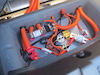
Thanks for the ideas... To get started on chasing things down, I drew up a diagram of my HV and power connections for the desktop charger testing.
1. Charger Case Earth
- The 'primary' earth for the charger case would be via the case on the HVJB, which gets earth from the J1772. The orange ground line in the diagram connects the cases to the GND (companion to the 12v) supply to the Gen2V3 charger controller card. If I don't include this ground connection then the Gen2V3 card cannot accurately detect the PROX status (if oscillates between connected and button pressed - which I guess is floating).
- Ground for the building (my house) runs back to the main panel and to a copper earth rod (nothing unusual).
- I ran the 12v to the Charger Gen2V3 card off a PSU that runs from 120v house power, generating 12v up to 60A.
2. Alternative EVSE
- I only have one EVSE installed at the house. I use it daily to charge my Fiat 500e.
Thanks for the help
Jeff
Thanks for the ideas... To get started on chasing things down, I drew up a diagram of my HV and power connections for the desktop charger testing.
- The 'primary' earth for the charger case would be via the case on the HVJB, which gets earth from the J1772. The orange ground line in the diagram connects the cases to the GND (companion to the 12v) supply to the Gen2V3 charger controller card. If I don't include this ground connection then the Gen2V3 card cannot accurately detect the PROX status (if oscillates between connected and button pressed - which I guess is floating).
- Ground for the building (my house) runs back to the main panel and to a copper earth rod (nothing unusual).
- I ran the 12v to the Charger Gen2V3 card off a PSU that runs from 120v house power, generating 12v up to 60A.
2. Alternative EVSE
- I only have one EVSE installed at the house. I use it daily to charge my Fiat 500e.
Thanks for the help
Jeff

Re: Tesla Charger Support Thread
I would drop the evse and test it in manual mode, connected directly to mains without contactors.
Then you can try without ground from the mains (if mains ground is a problem)
Thomas A. Edison “I have not failed. I've just found 10,000 ways that won't work"
-
Kevin Sharpe
- Posts: 1345
- Joined: Fri Dec 14, 2018 9:24 pm
- Location: Ireland and US
- Been thanked: 4 times
Re: Tesla Charger Support Thread
That's interesting... can you try replacing the 12V power supply for the controller card with a car battery? Maybe the power supply you're using has a leak to ground.
Any possibility your BMS is providing a leakage path to mains earth? Does anything change if you use the same power supply for the controller card and the BMS? What happens if you use a car battery to power both systems?
How thick is the ground wire from the J1772 socket to the Junction Box case? Can you verify the connection from the J1772 socket to the Junction Box case has a low resistance? Same with the ground connection from the Junction Box to the Charger.
Do you have a computer plugged into the USB port? If you do how is that grounded?
This is a personal post and I disclaim all responsibility for any loss or damage which any person may suffer from reliance on the information and material in this post or any opinion, conclusion or recommendation in the information and material.
-
Kevin Sharpe
- Posts: 1345
- Joined: Fri Dec 14, 2018 9:24 pm
- Location: Ireland and US
- Been thanked: 4 times
Re: Tesla Charger Support Thread
Something wrong here. Can you measure the pilot signal and ground at the J1772 connector without any connection to the charger? You're looking for a solid +/- 12V signal.DrJeff wrote: ↑Fri Oct 25, 2019 4:13 amSo I stuck an oscilloscope on the control pilot line from the EVSE (with a reference ground back to the GND on the charger). When the EVSE was not activated the amplitude of the square wave was 20V (??? expected 12V). When the EVSE was activated the square wave amplitude fell to 17V. I only use the oscilloscope once in a blue moon so please correct me if I'm reading this wrong.
See Basics of SAE J1772 (here)
This is a personal post and I disclaim all responsibility for any loss or damage which any person may suffer from reliance on the information and material in this post or any opinion, conclusion or recommendation in the information and material.
-
Kevin Sharpe
- Posts: 1345
- Joined: Fri Dec 14, 2018 9:24 pm
- Location: Ireland and US
- Been thanked: 4 times
Re: Tesla Charger Support Thread
Tom, are you aware of anyone who has tested >32A single phase?
This is a personal post and I disclaim all responsibility for any loss or damage which any person may suffer from reliance on the information and material in this post or any opinion, conclusion or recommendation in the information and material.
-
Kevin Sharpe
- Posts: 1345
- Joined: Fri Dec 14, 2018 9:24 pm
- Location: Ireland and US
- Been thanked: 4 times
Re: Tesla Charger Support Thread
This is good advice... eliminating the EVSE will tell us a lot about the issue.
This is a personal post and I disclaim all responsibility for any loss or damage which any person may suffer from reliance on the information and material in this post or any opinion, conclusion or recommendation in the information and material.
-
tom91
- Posts: 1308
- Joined: Fri Mar 01, 2019 9:15 pm
- Location: Bristol
- Has thanked: 103 times
- Been thanked: 216 times
Re: Tesla Charger Support Thread
No I am not, but with an EVSE signal generator, a crude one, I did measure the full range and look at the control board response and found no wierd behaviour.Kevin Sharpe wrote: ↑Tue Oct 29, 2019 9:32 amTom, are you aware of anyone who has tested >32A single phase?
-
Kevin Sharpe
- Posts: 1345
- Joined: Fri Dec 14, 2018 9:24 pm
- Location: Ireland and US
- Been thanked: 4 times
Re: Tesla Charger Support Thread
Many thankstom91 wrote: ↑Tue Oct 29, 2019 12:54 pmNo I am not, but with an EVSE signal generator, a crude one, I did measure the full range and look at the control board response and found no wierd behaviour.Kevin Sharpe wrote: ↑Tue Oct 29, 2019 9:32 amTom, are you aware of anyone who has tested >32A single phase?
This is a personal post and I disclaim all responsibility for any loss or damage which any person may suffer from reliance on the information and material in this post or any opinion, conclusion or recommendation in the information and material.
Re: Tesla Charger Support Thread
I can easily enough connect the charger to 120VAC directly, getting a 240 line will take a little effort. But I think the 120Vac should do the trick as far as eliminating EVSE issues.Kevin Sharpe wrote: ↑Tue Oct 29, 2019 9:35 amThis is good advice... eliminating the EVSE will tell us a lot about the issue.
Jeff
Re: Tesla Charger Support Thread
When connected to the Proximity line on the controller card, I'm getting +9-12V which is consistent with the EV Connected Ready signal. When I disconnect from the Gen2V3 card (so EVSE connected to nothing I get +12V - no square wave. I used the GND connection from the EVSE to baseline these measurements. Tomorrow I'm going to check the consistency between the GND connections in the garage (I saw a slight difference when measuring yesterday which used a GND from a separate line. All the lines are all feed from the same sub-panel.Kevin Sharpe wrote: ↑Tue Oct 29, 2019 9:24 amSomething wrong here. Can you measure the pilot signal and ground at the J1772 connector without any connection to the charger? You're looking for a solid +/- 12V signal.DrJeff wrote: ↑Fri Oct 25, 2019 4:13 amSo I stuck an oscilloscope on the control pilot line from the EVSE (with a reference ground back to the GND on the charger). When the EVSE was not activated the amplitude of the square wave was 20V (??? expected 12V). When the EVSE was activated the square wave amplitude fell to 17V. I only use the oscilloscope once in a blue moon so please correct me if I'm reading this wrong.
See Basics of SAE J1772 (here)
Jeff