Tesla Model 3 Rear Drive Unit Hacking
-
Roadstercycle
- Posts: 118
- Joined: Mon Sep 23, 2019 10:28 pm
- Location: California
- Has thanked: 3 times
- Been thanked: 2 times
- Contact:
Re: Tesla Model 3 Rear Drive Unit Hacking
Zero EV is working with Ingenext so they can have a unit to put there name on. Same unit different branding. Probably the same price I would imagine.
-
collin80
- Posts: 110
- Joined: Sun Aug 30, 2020 3:28 pm
- Location: United States, Michigan
- Been thanked: 6 times
- Contact:
Re: Tesla Model 3 Rear Drive Unit Hacking
I don't have a model 3 motor to test or I would. I reached out to people I know who have experience with various Tesla parts. Nobody knows the answer in definite details. The best I can get out of anyone is that Tesla knew that the motor back EMF far exceeds the standoff rating of the SiC FETs and so without the normal built-in shorting of the motor that is supposed to happen upon power failure it will exceed the FET rating and blow them up. So, I don't have a hard and concrete number for the EMF but it sounds like "too much" is the general answer.
Re: Tesla Model 3 Rear Drive Unit Hacking
Happy holidays,
wanted to check in if there is currently more work done. My conversion planning advanced and I am about to buy a DU. I do program for living, as hobby done lots of oldtimer repair, but also open source designs of lots of simple digital circuits on the level of the openinverter SDU board, low level bare micro controllers development with CAN/SPI, etc. Don't know the C2000 yet but looked at collin80's port and list of outstanding work items on github.
Alternative for me is the S/X SDU board. And before I engage in this project and buy a M3 DU instead - which would fit my chassis so much better - I was wondering how the current feeling is about the feasibility of finalizing some first working version and the amount of actual
work and complexity/challenges remaining? I can and am willing to engage. But maybe you folks don't work on this currently, don't have time, lost interest or just went stealth mode for other reasons?
Cheers,
Bernd
-
Jack Bauer

- Posts: 3665
- Joined: Wed Dec 12, 2018 5:24 pm
- Location: Ireland
- Has thanked: 11 times
- Been thanked: 347 times
- Contact:
Re: Tesla Model 3 Rear Drive Unit Hacking
Still very much alive. Just needs time and resources like all projects so welcome aboard.
I'm going to need a hacksaw
-
Jack Bauer
- Posts: 3665
- Joined: Wed Dec 12, 2018 5:24 pm
- Location: Ireland
- Has thanked: 11 times
- Been thanked: 347 times
- Contact:
Re: Tesla Model 3 Rear Drive Unit Hacking
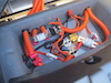
dsp1108 asked me to post this video and info:
Sensor temperature of motor like as ntc vishay.
Connect to pin 18 and 28 signal connector invertor.
R 25 =100 k.
Sensor temperature of motor like as ntc vishay.
Connect to pin 18 and 28 signal connector invertor.
R 25 =100 k.
- Attachments
-
I'm going to need a hacksaw
Re: Tesla Model 3 Rear Drive Unit Hacking
Sorry for potentially redundant or stupid questions and a too long read.
Do I initially have to bother and learn more about the TLF35584? Do we know if the controller and periphery is supplied with power permanently without the PMIC being configured? Or, Dave, is your code 100% functional? Wondering if e.g. watchdogs kick in and shut down power without config. Has anyone tested the code on an inverter (it is still stm32 based)?
Otherwise I'll focus on the position readings first unless I missed it already works. Hope it is a feasible goal without a DU controller connected for comparison.
A xxx990-00-G rear DU is on it's way (TC-2 as undesired backup plan b). Hirose connector housings are currently backorder only. Will try with the individual crimp pins on the JTAG first.
So far, I got my own version of PWM and FOC with PI control running on a launchpad/boostxl, ported Dave's gate driver code to C2000 and the TI compiler (maybe I just missed an existing port?). CAN runs for potentially writing out monitoring data. Together some satisfying to watch patterns on the Saleae. In lack of any handy alternative I used a BLDC w/o position sensing, it even turns with fixed theta (badly obviously). Would prefer using open source and vscode. But for a start CCStudio felt easier and I guess CLA and other specialties work better.
-
johu

- Site Admin
- Posts: 6739
- Joined: Thu Nov 08, 2018 10:52 pm
- Location: Kassel/Germany
- Has thanked: 380 times
- Been thanked: 1562 times
- Contact:
Re: Tesla Model 3 Rear Drive Unit Hacking
The new route is porting the openinverter code to the TI controller to avoid taking the chip off the board. There is a port, a link to it is hidden in this thread somewhere
Support R/D and forum on Patreon: https://patreon.com/openinverter - Subscribe on odysee: https://odysee.com/@openinverter:9
-
davefiddes
- Posts: 294
- Joined: Mon Jan 18, 2021 12:39 pm
- Location: Edinburgh, Scotland, UK
- Has thanked: 77 times
- Been thanked: 95 times
Re: Tesla Model 3 Rear Drive Unit Hacking
To get the gate drivers to turn on we'll need to get the TLF35584 configured and strobe the watchdog every 100ms (IIRC). I've got a driver I put together for the STM32 here but this hasn't been refactored for the C2000 or run against real hardware.fbo wrote: ↑Mon Jan 31, 2022 8:40 am Sorry for potentially redundant or stupid questions and a too long read.
Do I initially have to bother and learn more about the TLF35584? Do we know if the controller and periphery is supplied with power permanently without the PMIC being configured? Or, Dave, is your code 100% functional? Wondering if e.g. watchdogs kick in and shut down power without config. Has anyone tested the code on an inverter (it is still stm32 based)?
I reorganised my repos last week to remove the "portable-cpp" branch from my stm32-sine fork and put it in its own repo: https://github.com/davefiddes/c2000-inverter. It's the same underlying repo and a fork of johu's stm32-sine but having a separate repo makes it clear that it's a fork. Didn't realise anyone else was working on this otherwise I would have publicised the change. You'll need to do a
Code: Select all
git remote add upstream https://github.com/davefiddes/c2000-inverterMy code currently runs on the Tesla M3 inverter from RAM (so you don't need to wipe the flash if you are careful- see docs). The core inverter runs with a hard coded shaft angle and zero speed to allow PWM testing. The PWM signals appear on the outside of the chip and viewed with a scope. I am working on getting the STGAP1AS gate driver chips configured or I was until I got fed up banging my head against the wall trying...must get back to that. With the gate drivers working and the PMIC operating and a HV DC supply connected it should be possible to get PWM on the inverter outputs. This is my short term goal.
This would be a good thing to work on I think. Analog capture is intrinsically linked with the PWM on the C2000. I'm done working on the PWM for now so should be OK to work on the ADC side of things.
Would strongly recommend buying or building a JTAG adapter to Damien's design. The Hirose connectors are an utter pain to work with otherwise.
CCStudio is the only realistic game in town for working running and debugging on the C2000. FWIW I use VS Code for writing most code, debugging unit tests and such.fbo wrote: ↑Mon Jan 31, 2022 8:40 am So far, I got my own version of PWM and FOC with PI control running on a launchpad/boostxl, ported Dave's gate driver code to C2000 and the TI compiler (maybe I just missed an existing port?). CAN runs for potentially writing out monitoring data. Together some satisfying to watch patterns on the Saleae. In lack of any handy alternative I used a BLDC w/o position sensing, it even turns with fixed theta (badly obviously). Would prefer using open source and vscode. But for a start CCStudio felt easier and I guess CLA and other specialties work better.
Re: Tesla Model 3 Rear Drive Unit Hacking
Thanks for the quick and very helpful response.
 Just the sequence and timing of HV start in relation to powering on the board could matter. Wondering also what the minimum switchable voltage would be to see some output on the scope or turn the engine.
Seems delivery of the DU is scheduled for tomorrow.
Got it, maybe first step then. I also found the respective info in the datasheet now as well. For the ease of testing it could be easiest to just pacify the watchdog by switching it off during init.davefiddes wrote: ↑Mon Jan 31, 2022 1:41 pm To get the gate drivers to turn on we'll need to get the TLF35584 configured and strobe the watchdog every 100ms (IIRC). I've got a driver I put together for the STM32 here but this hasn't been refactored for the C2000 or run against real hardware.
Yes, used that already. I thus just cherry picked and ported files I really needed to get started though.davefiddes wrote: ↑Mon Jan 31, 2022 1:41 pm I reorganised my repos last week to remove the "portable-cpp" branch from my stm32-sine fork and put it in its own repo: https://github.com/davefiddes/c2000-inverter. [...]
Got it. Thanks for explaining. It is scary to try and error with a $ 1.6k board. What could go wrongdavefiddes wrote: ↑Mon Jan 31, 2022 1:41 pm [...] With the gate drivers working and the PMIC operating and a HV DC supply connected it should be possible to get PWM on the inverter outputs. This is my short term goal.
I do have ADC working from PWM on my launchpad. Still need to investigate which compare value (zero, max) exactly should trigger the sample timing wise. But moved that to testing on the inverter.davefiddes wrote: ↑Mon Jan 31, 2022 1:41 pm This would be a good thing to work on I think. Analog capture is intrinsically linked with the PWM on the C2000. I'm done working on the PWM for now so should be OK to work on the ADC side of things.
Planning to use the Launchpad for JTAG as it is much cheaper. I have wires crimped to the Hirose contacts and isolated them with thin shrink tube. Veeeery painful. Just the housing missing, they should still stay in place as they are very tight clamps. The Harwin M40 seem to be the better option, in stock and already coming with 32 AWG crimped on.davefiddes wrote: ↑Mon Jan 31, 2022 1:41 pm Would strongly recommend buying or building a JTAG adapter to Damien's design. The Hirose connectors are an utter pain to work with otherwise.
Seems delivery of the DU is scheduled for tomorrow.
-
davefiddes
- Posts: 294
- Joined: Mon Jan 18, 2021 12:39 pm
- Location: Edinburgh, Scotland, UK
- Has thanked: 77 times
- Been thanked: 95 times
Re: Tesla Model 3 Rear Drive Unit Hacking
The thing that makes the TLF35584 a safety PSU is that it's operation is hard wired to the internal state machine. When it starts it comes up in the INIT state with all of the supply rails operating. To enable the gate drive it needs to assert the SS2 signal. The only way to do this is to enable and strobe the watchdog. Also, it's a window watchdog so you have a +/- 50ms window either side to hit otherwise it gets upset. Easy enough to do but not avoidable.
Should be reasonably robust provided the gate drivers are configured correctly. I think Damien figured that you needed to get 60-70V before the backup gate drive PSU would fully operate. I think that the gate drivers should be fine with a lower DC voltage for playing on the bench.fbo wrote: ↑Mon Jan 31, 2022 6:45 pm Got it. Thanks for explaining. It is scary to try and error with a $ 1.6k board. What could go wrong
Zero is value that marks the center of the PWM cycle when we should capture the current readings.
Good luck.
Re: Tesla Model 3 Rear Drive Unit Hacking
DU arrived. David, you were right on the JTAG. Waiting for a real connector now. Over night all Launchxls sold out btw.
Taking the time to port PMIC code to C2000. In the meantime I wrote a small script converting the logicdata SPI files. The script and conversions of the mcu reset, cold start and run can be found here:
https://github.com/ocklin/Tesla-Model-3 ... 4QVVS2_SPI
Since we have FWD cycle 250ms, WWD CW 50ms and OW 100ms they seem to follow this pattern:
In the port I already split the two functions. Once tested on HW I'll raise a pull request.
Taking the time to port PMIC code to C2000. In the meantime I wrote a small script converting the logicdata SPI files. The script and conversions of the mcu reset, cold start and run can be found here:
https://github.com/ocklin/Tesla-Model-3 ... 4QVVS2_SPI
Since we have FWD cycle 250ms, WWD CW 50ms and OW 100ms they seem to follow this pattern:
Code: Select all
loop:
  100ms
  write WWD
  read  FWD quest

  100ms
  write WWD
  write FWD answer
-
davefiddes
- Posts: 294
- Joined: Mon Jan 18, 2021 12:39 pm
- Location: Edinburgh, Scotland, UK
- Has thanked: 77 times
- Been thanked: 95 times
Re: Tesla Model 3 Rear Drive Unit Hacking
That's bad luck on the LaunchXL board. Any FT2232H board should be possible to wire up provided you can get at the required pins. I ended up with an official FTDI FT2232H-56Q MINI MODULE eval board because that's what was available. There may be other options on ebay, etc given how popular these chips are for openocd JTAG boards.
I wrote a bunch of analyser programs for the SPI captures but forgot to release them. Sorry. The watchdog behaviours you observe make more sense.
I'm sure Damien will be quite happy to merge any updates you have when he gets a moment.
Also, Quite happy to test any PRs on my hardware until you get your own inverter wired up.
Made a huge step forward today on my side with the gate driver code. Found the annoying bug(s) that were messing up comms with the STGAP1AS gate driver chain. Managed to get the red fault LED that's been on solid since the autumn to go out! Once I get the code cleaned up we should have a basic (but safe) gate driver.
Re: Tesla Model 3 Rear Drive Unit Hacking
I still have one but thought of a backup one. There are also 20$ smaller Lauchxls available with the same FT chip, they are still available.
Great news. I only now discovered your C2000 port of the gate driver driver in the test dir. Missed it and did my own port :/davefiddes wrote: ↑Thu Feb 03, 2022 2:35 pm Made a huge step forward today on my side with the gate driver code. Found the annoying bug(s) that were messing up comms with the STGAP1AS gate driver chain. Managed to get the red fault LED that's been on solid since the autumn to go out! Once I get the code cleaned up we should have a basic (but safe) gate driver.
Now, a question. I tried to power the board on unswitched 12V on pin 22 and GND on pin 13. Anything I should expect to happen? Like a LED turning on? Something I am missing?
-
davefiddes
- Posts: 294
- Joined: Mon Jan 18, 2021 12:39 pm
- Location: Edinburgh, Scotland, UK
- Has thanked: 77 times
- Been thanked: 95 times
Re: Tesla Model 3 Rear Drive Unit Hacking
Damien or I haven't figured that out yet. I also tried to power the unit via that to start with and it consumed no current. It's a very thin wire so likely used for stand-by operation. I wonder if there is a GPIO hooked up to a mosfet that the MCU can use to enable stand-by. Not quite sure what benefit there is to running the unit all the time. Probably something to do with remote firmware updates or other scary stuff.
-
Jack Bauer
- Posts: 3665
- Joined: Wed Dec 12, 2018 5:24 pm
- Location: Ireland
- Has thanked: 11 times
- Been thanked: 347 times
- Contact:
Re: Tesla Model 3 Rear Drive Unit Hacking
Excellent work Dave:) You need switched and permanent 12v to fire up the inverter. See my github for the pinout.
I'm going to need a hacksaw
-
Jack Bauer
- Posts: 3665
- Joined: Wed Dec 12, 2018 5:24 pm
- Location: Ireland
- Has thanked: 11 times
- Been thanked: 347 times
- Contact:
Re: Tesla Model 3 Rear Drive Unit Hacking
Also for those struggling with the JTAG connector who may not want to buy the adapter board kit from me the design files are fully opensource :
https://github.com/damienmaguire/Tesla- ... re/JTAG_TI
https://github.com/damienmaguire/Tesla- ... re/JTAG_TI
I'm going to need a hacksaw
Re: Tesla Model 3 Rear Drive Unit Hacking
The switched 12V does indeed do the trick. I had tried that initially as well but without result. Problem was the connector though that was not sitting tight enough, fixed now.
Testing rotor angle measurement may become sort of a chicken egg problem. Coil part of the sensor can easily be removed and sits on my desk, but the actuator (?) sits (unremovably?) tight on the rotor. I am too weak to turn the rotor manually even when removed from the case and detached from the gearbox.
Without PWM or something else driving the rotor (lever or another strong motor maybe?) it will be difficult to test. After FOC experiments with launchxl/boostxl turning even DC motors without position feedback I am confident we can do the same with the Tesla rotor without position data as well. This should be maybe the focus first.
@Dave, I wrote a scheduler, used it in my C2000 port of the pmic driver, templated the same, separated out the SPI HW handling into a separate class for easier testing/mocking. Should do the same with the gate driver. But maybe you have come further? Okay for me to do some double work initially to ramp up on the code.
The more I learn about the beast the more I am impressed by all the re-engineering work everyone has already done.
-
davefiddes
- Posts: 294
- Joined: Mon Jan 18, 2021 12:39 pm
- Location: Edinburgh, Scotland, UK
- Has thanked: 77 times
- Been thanked: 95 times
Re: Tesla Model 3 Rear Drive Unit Hacking
I pushed my working gate driver code this afternoon having got it properly tested. Lots of fun. Who would have thought that random unused bits would flip in the status registers each time you read them. All seems to behave sensibly now in normal operation and various fault conditions. Most of the irritations that made it take so long were down to me not being used to not having an 8-bit type when dealing with an 8-bit peripheral. FML.
If you could share your PMIC driver @fbo that would be great. That's my next target so I can get the basic inverter running with a DC supply and see I can get PWM on the phase connections.
If you could share your PMIC driver @fbo that would be great. That's my next target so I can get the basic inverter running with a DC supply and see I can get PWM on the phase connections.
Re: Tesla Model 3 Rear Drive Unit Hacking
I parked the code here to not loose it: https://github.com/ocklin/tesla-m3-driver
Hopefully I get around to move it the inverter project next days.
Got blinky running on the Tesla board now. So, finally set up with the XDS100v2 from the launchxl and a M40 connector with pre-crimped wires.
Hopefully I get around to move it the inverter project next days.
Got blinky running on the Tesla board now. So, finally set up with the XDS100v2 from the launchxl and a M40 connector with pre-crimped wires.
Re: Tesla Model 3 Rear Drive Unit Hacking
Raised a PR https://github.com/davefiddes/c2000-inverter/pull/1 for the PMIC port.
Doesn't seem to do the job yet though but uses right SPI ports. Need to verify if I didn't switched e.g. simo/somi. Also noticed that sdi/mosi is pulled low at wrong times.
Doesn't seem to do the job yet though but uses right SPI ports. Need to verify if I didn't switched e.g. simo/somi. Also noticed that sdi/mosi is pulled low at wrong times.
Re: Tesla Model 3 Rear Drive Unit Hacking
SS1 and SS2 remain on now. Required quite a few fixes and I probably introduced those problems first in my port. A fake PmicSpiDriver and test prg were key in debugging though.
I'll see which changes actually finally did the trick and will raise a new PR tomorrow.
I'll see which changes actually finally did the trick and will raise a new PR tomorrow.
-
davefiddes
- Posts: 294
- Joined: Mon Jan 18, 2021 12:39 pm
- Location: Edinburgh, Scotland, UK
- Has thanked: 77 times
- Been thanked: 95 times
Re: Tesla Model 3 Rear Drive Unit Hacking
That sounds like good progress. Unit tests make all the difference. At least you can be sure that the code behaves somewhat like you intended it to...
No need to raise a separate PR, just add to the existing one.
No need to raise a separate PR, just add to the existing one.
Re: Tesla Model 3 Rear Drive Unit Hacking
Probably won't get much around to it today.
Btw, did you get PWM running on the inverter with inverter-main.cpp? It was a quick experiment only but I don't. Even when strobing the wd (and moving performancemetrics to different timer which is conflicting with scheduler). But it works on the launchxl.
Btw, did you get PWM running on the inverter with inverter-main.cpp? It was a quick experiment only but I don't. Even when strobing the wd (and moving performancemetrics to different timer which is conflicting with scheduler). But it works on the launchxl.
-
davefiddes
- Posts: 294
- Joined: Mon Jan 18, 2021 12:39 pm
- Location: Edinburgh, Scotland, UK
- Has thanked: 77 times
- Been thanked: 95 times
Re: Tesla Model 3 Rear Drive Unit Hacking
Curious. Just checked and it's working fine on my inverter. As explained it only shows up on the MCU pins for now. It's not going to show up on the phases or even the gate driver inputs until the gate driver and PMIC are configured and the global PWM enable GPIO is asserted. As Damien explained in his videos there are a lot of safety interlocks on the inverter to stop bad things happening udring reboots, power up, etc.