Start at the BMS connector and and figure out which module connector is number 1.
You have created yourself a whole lot of hassle by marking any of the connectors. Colors mean nothings, you need to figure out the pin out.
You will find some are duplicated cell taps as the idea is to use the most positive of the previous cell group as the most negative for the next cell group.
[WIP] Mercedes 310E (310D campervan) - GS450H/GS300H
-
Jacobsmess
- Posts: 490
- Joined: Thu Mar 02, 2023 1:30 pm
- Location: Uk
- Has thanked: 253 times
- Been thanked: 62 times
Re: [WIP] Mercedes 310E (310D campervan) - GS450H/GS300H
This is part of the problem, it seems there are multiple options for certain connectors with the same pin out and the same connector type. The modules are numbered sequentially on their part number but theres no certainty that they were in that order. I'll hopefully get a bit more time this evening to do some more work on them. Other than pinout, connector comparability and number, what might be a way of ordering them?
Yep, lesson learned more pictures less enthusiastic dismantling.
Thanks that makes sense.
-
Jacobsmess
- Posts: 490
- Joined: Thu Mar 02, 2023 1:30 pm
- Location: Uk
- Has thanked: 253 times
- Been thanked: 62 times
Re: [WIP] Mercedes 310E (310D campervan) - GS450H/GS300H
Ok so the more I look the more confused I am and I keep coming back to the same issue, the BMS side connectors that connect to the battery's don't match the pin outs (regardless of colours) to some of the batteries. In fact, most don't match. Some do but others don't and these are cell taps that are missing rather than thermistor connections.
So I'm pretty sure I'm right on that the lexus battery pack did not have monitoring setup for every cell set of 3. Which tbh, seems ludicrous, I suspect it is a manufacturing error but I'm fairly confident that this is the case because as said. . Edited: upon pondering more this is not going to be right.
there are taps on the cells that are not there on the BMS side of things.... Although now I'm thinking back to what Tom said, could some of the taps on the cells be redundant as only 9 taps are needed for the larger packs.
Anyway, I'm also thinking, is this all necessary, the main thing is that with whatever BMS I implement, all cells are tap'd, the order doesn't matter does it?
-
Jacobsmess
- Posts: 490
- Joined: Thu Mar 02, 2023 1:30 pm
- Location: Uk
- Has thanked: 253 times
- Been thanked: 62 times
Re: [WIP] Mercedes 310E (310D campervan) - GS450H/GS300H
Apologies for the learning out loud going on here. I'm definitely a kinesthetic learner ...
-
tom91
- Posts: 1308
- Joined: Fri Mar 01, 2019 9:15 pm
- Location: Bristol
- Has thanked: 103 times
- Been thanked: 216 times
Re: [WIP] Mercedes 310E (310D campervan) - GS450H/GS300H
Uhmm you are quite wrong. Cells in parallel get monitored togethor as a set.
I said map the connectors of the BMS slave module. figure out with pins are cell connections by looking at the circuits and work back from there.
Did you create a spreadsheet with module part number and pin out info yet to have an overview?
I said map the connectors of the BMS slave module. figure out with pins are cell connections by looking at the circuits and work back from there.
Did you create a spreadsheet with module part number and pin out info yet to have an overview?
-
jrbe
- Posts: 287
- Joined: Mon Jul 03, 2023 3:17 pm
- Location: CT, central shoreline, USA
- Has thanked: 99 times
- Been thanked: 74 times
Re: [WIP] Mercedes 310E (310D campervan) - GS450H/GS300H
There's a million ways to do things. If what you're doing is a stretch from your comfort zone you have to play off your strengths which might look odd to some.
It's good you found the thermistors.
If you're good with Excel:
You can label columns with pin numbers.
Mark out anything consistent, the thermistors and others that you know in the second column labeled voltages. 3rd column is cell group. Add a spot to identify different connectors / sections of battery. Print that big enough to write on.
Grab a pencil so you can erase.
Work on low voltage pairs only. Keep it under 60v or so if you can.
Set your meter to volts DC and make sure the probe wires are in their correct positions in the meter to read DC.
Connect the black probe of your meter to the 0v / negative of that section of the battery.
Using the red probe wire, read and record the voltage reading on each connector position of your BMS connector on your sheet in the proper spot. Voltage reading doesn't have to be past the decimal point. I don't think you would damage anything doing this.
Enter that all into Excel. Sort by voltage. Excel just did a big chunk of the struggle for you.
Make sure you see it increment by around 2.5-4v on each step. Any bigger jumps mean a missing wire or some electrical wizardry that needs to be figured out.
If you have properly incrementing steps you can then label the cell groups. Don't do this if you have missing steps. You number each battery voltage step in Excel. Each tap is between cell groups, think of it as counting battery spacers if it helps.
Now you can sort by connector position or cell group.
You'll have a few 0v positions. Those are what's left to figure out what they do.
-
royhen99
- Posts: 211
- Joined: Sun Feb 20, 2022 4:23 am
- Location: N. Wiltshire. UK
- Has thanked: 16 times
- Been thanked: 101 times
Re: [WIP] Mercedes 310E (310D campervan) - GS450H/GS300H
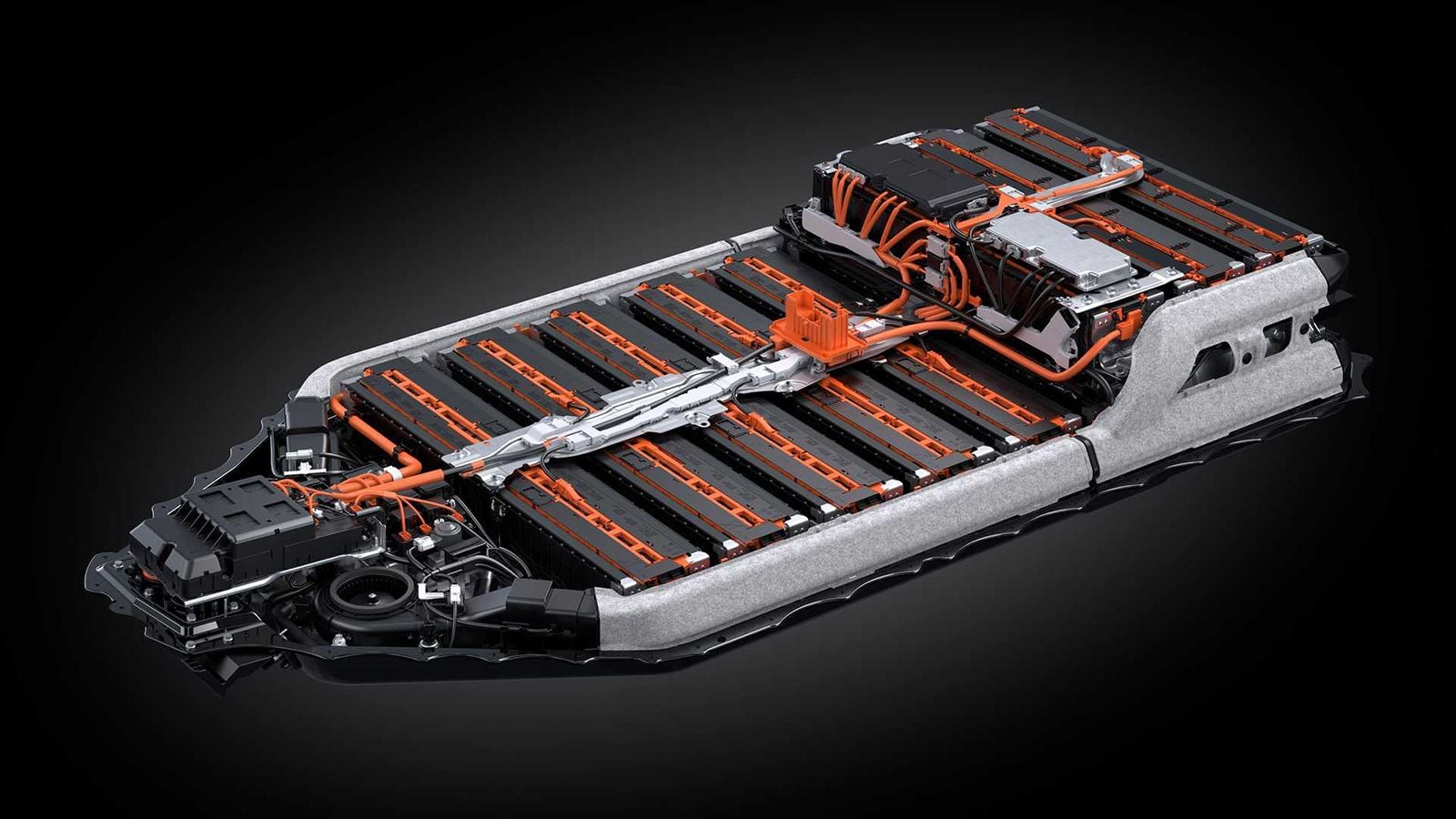
Having looked at this a bit it seems you do not need to know the connections at the battery voltage sensor module or the battery modules as the connections are all routed though the intermediate wiring loom. If the three 8s modules are the same then they just plug into the 3 smaller connectors in the intermediate loom and that takes care of connecting the additional cell tap as required. Similarly for 9s modules only there are two types. Just find which connectors in the intermiatiate loom have 17 connections and connect the appropriate module. There is probably only one ( maybe two with 17 connections) as most of the modules do not get split across two different BMS chips. When you come to join the modules together the order becomes important but from this photo it does not look too difficult to work out, only the connection beween the 9s and 8s modules is not that clear.
https://cimg3.ibsrv.net/cimg/www.cluble ... 596431.jpg
https://cimg3.ibsrv.net/cimg/www.cluble ... 596431.jpg
-
Jacobsmess
- Posts: 490
- Joined: Thu Mar 02, 2023 1:30 pm
- Location: Uk
- Has thanked: 253 times
- Been thanked: 62 times
Re: [WIP] Mercedes 310E (310D campervan) - GS450H/GS300H
So I had some time to try and write some of the above up on an excel sheet.
Essentially, the BMS has 5 groups,
The harness has 6 connectors on the BMS side one black group of 3 (B1, B2, B3) and one white group of 3 (W1, W2, W3)
These go to 11 module connectors. Of these there are 4 different layouts, A, B, C and D
(I've guessed the potential module numbers on the attachment given their placement and number of terminals to cells but it doesn't match up neatly... for example,
Worth noting is that there are 5 grouped and crimped/ultrasonically welded wires mid-harness (8xpink, 7xred, 7xpurple, 8xblue and 8xwhite) that are thermistors, which I believe are the negative half of the thermistor pairs with a common then returning to the BMS (38 wires grouped with 33 from the batteries and 5 to the BMS)
Essentially, the BMS has 5 groups,
 Book1.pdf
- (326.58 KiB) Downloaded 24 times
These go to 11 module connectors. Of these there are 4 different layouts, A, B, C and D
(I've guessed the potential module numbers on the attachment given their placement and number of terminals to cells but it doesn't match up neatly... for example,
- group 1 - modules 22, 23 and 24 have 24 cells in 8s3p with 16 cell connections (6 thermistors, 3 negative cell taps and 7 positive cell taps).
- group 2 - modules 25 and 27 have 27 cells in 9s3p with 16 cell connections (6 thermistors, 2 negative cell taps and 8 positive cell taps).
- group 3 - modules 26, 28, 29, 30, 31 and 32 have 27 cells in 9s3p with 17 cell connections (6 thermistors, 2 negative cell taps and 9 positive cell taps).
- Type A - 16 pins (matching group 1 on the battery connectors)
- Type B - 15 pins (matching none of the battery connectors but I suspect connect to 2 of group 1)
- Type C - 17 pins (matching group 3 on the battery connectors)
- Type D - 16 pins (matching none of the battery connectors but I suspect connect to 5 of group 3)
Worth noting is that there are 5 grouped and crimped/ultrasonically welded wires mid-harness (8xpink, 7xred, 7xpurple, 8xblue and 8xwhite) that are thermistors, which I believe are the negative half of the thermistor pairs with a common then returning to the BMS (38 wires grouped with 33 from the batteries and 5 to the BMS)
-
Jacobsmess
- Posts: 490
- Joined: Thu Mar 02, 2023 1:30 pm
- Location: Uk
- Has thanked: 253 times
- Been thanked: 62 times
Re: [WIP] Mercedes 310E (310D campervan) - GS450H/GS300H
So I've spent a decent chunk of today buzzing between the battery side and the BMS side of the harness and have it all mapped out. Unfortunately this doesn't tell me anything as I am still unsure if which battery module side connector connects to which module... I was hoping to see an obvious pattern across the 6 BMS connectors of cell taps and temp sensors but it's certainly not clear to me. This might be the way I have it drawn out and I'll redraw it again in the form of the actual connectors (currently it's just a long list) which might make it clear but currently I'm struggling to see any groups or order. For instance, some connectors have cell taps from 3 different modules which I was not expecting!
-
Jacobsmess
- Posts: 490
- Joined: Thu Mar 02, 2023 1:30 pm
- Location: Uk
- Has thanked: 253 times
- Been thanked: 62 times
Re: [WIP] Mercedes 310E (310D campervan) - GS450H/GS300H
On another note, I got my ISA Shunt up and running and also a mitsubishi outlander OBC turned up this morning and is sat in my kitchen (until tomorrow when my partner gets back from her trip haha)....
-
Jacobsmess
- Posts: 490
- Joined: Thu Mar 02, 2023 1:30 pm
- Location: Uk
- Has thanked: 253 times
- Been thanked: 62 times
Re: [WIP] Mercedes 310E (310D campervan) - GS450H/GS300H
Right, I've cracked it with the help of Lexus Tech wiring diagrams. I remembered Damian mentioning these were available for 24hrs access online so found them and did a lot of digging around and I've managed to workout which modules connect to which connectors and their order.... finally!
All brought together by the use of the wire colours mainly. I've only fully confirmed the order of the 3x24s3p modukes but should be able to work out the others now as well.
All brought together by the use of the wire colours mainly. I've only fully confirmed the order of the 3x24s3p modukes but should be able to work out the others now as well.
-
Jacobsmess
- Posts: 490
- Joined: Thu Mar 02, 2023 1:30 pm
- Location: Uk
- Has thanked: 253 times
- Been thanked: 62 times
Re: [WIP] Mercedes 310E (310D campervan) - GS450H/GS300H
So I've got family visitng so I did what most others here would do and took over the living room table to work on my CANbus logging setup. Again with help from BigPie, I managed to get Savvycan logging with Uhis wifican (ESP32RET) tool. I verified my canbus network was working by giving a heartbeat to the mitsubishi outlander charger then plugged in the Lexus UX300E BMS (both units) and did some wire tracing to see what was required to get them to power up. After a lot of scouring the wiring diagrams I found the main BMS needs 2 +12V ignition signals and 3 ground signals and it starts firing out CAN messaged.
CAN1 has a lot more IDs then CAN2, the BMS unit controls all the pack cooling as well as precharge and AC charge relays, battery heating pads, takes input from the current sensor and a few other bits...
I tried saving the log file but Savvycan crashes when I try to save, I'll have to sort that later but for now, I'll upload some photos of the logging. Nothing was hooked up at the time but I'll add some modules and do some more logging and see what changes.
-
Jacobsmess
- Posts: 490
- Joined: Thu Mar 02, 2023 1:30 pm
- Location: Uk
- Has thanked: 253 times
- Been thanked: 62 times
Re: [WIP] Mercedes 310E (310D campervan) - GS450H/GS300H
Can logs from the UX300E bms CAN1
- Attachments
-
-
-
-
tom91
- Posts: 1308
- Joined: Fri Mar 01, 2019 9:15 pm
- Location: Bristol
- Has thanked: 103 times
- Been thanked: 216 times
Re: [WIP] Mercedes 310E (310D campervan) - GS450H/GS300H
Okay, but why so many pictures of the laptop screen?
Did you note down what state the BMS was in when the log was taken? I presume you have not yet connected back up any of the cells.
Did you note down what state the BMS was in when the log was taken? I presume you have not yet connected back up any of the cells.
-
Jacobsmess
- Posts: 490
- Joined: Thu Mar 02, 2023 1:30 pm
- Location: Uk
- Has thanked: 253 times
- Been thanked: 62 times
Re: [WIP] Mercedes 310E (310D campervan) - GS450H/GS300H
To show all the can IDs in the "frame filtering" section I'm not sure if they mean anything to anyone or if they can be familiar to other Toyota can IDs. But the 3 images capture all the CAN1 IDs.
Nothing connected as of yet, I'll look to add the modules next and see if things change on the logs.
Here is CAN2 logs showing a lot less IDs....
-
tom91
- Posts: 1308
- Joined: Fri Mar 01, 2019 9:15 pm
- Location: Bristol
- Has thanked: 103 times
- Been thanked: 216 times
Re: [WIP] Mercedes 310E (310D campervan) - GS450H/GS300H
Please just post the CAN log. No point squinting at grainy screen pictures.
Best would be to create a github repository.
Best would be to create a github repository.
-
Jacobsmess
- Posts: 490
- Joined: Thu Mar 02, 2023 1:30 pm
- Location: Uk
- Has thanked: 253 times
- Been thanked: 62 times
Re: [WIP] Mercedes 310E (310D campervan) - GS450H/GS300H
Yes I will do once the family leave and I have time to mess with savvycan to stop it from crashing
-
Jacobsmess
- Posts: 490
- Joined: Thu Mar 02, 2023 1:30 pm
- Location: Uk
- Has thanked: 253 times
- Been thanked: 62 times
Re: [WIP] Mercedes 310E (310D campervan) - GS450H/GS300H
So I killed my can transceiver by giving to direct 12v accidentally so had to buy some more. After waiting about 2 weeks they finally arrived but now, using the same setup I'm getting nothing on the can. The BMS is drawing current, I can see a fluctuating 2.5V between gnd and canL and around 5v canH whilst using a multimeter.
I'm using Uhis wifican on a esp32 S3 board (previously I was using the esp32 s3 and that worked but now it doesn't so I'm trying the S3).
So as far as I can see with the tools I have, the BMS is drawing current, it is sending can (I can see the fluctuating voltage with a multimeter at the esp32 pins) but nothing is showing on savvycan. Any ideas on where/how is best to troubleshoot?
-
Jacobsmess
- Posts: 490
- Joined: Thu Mar 02, 2023 1:30 pm
- Location: Uk
- Has thanked: 253 times
- Been thanked: 62 times
Re: [WIP] Mercedes 310E (310D campervan) - GS450H/GS300H
I finally got some CanLogs after buying a better can transceiver, the 5 TJA1050 units I bought from Aliexpress were duds but the Waveshare one seems to be working nicely.
Anyway, my current thinking was I could just log can data whilst unplugging and plugging in modules and other things but I'm not 100% if this is the best appraoch.
I'm also logging all the can data from the main BMS atm, but I'm going to change tact and just log on the Voltage Sensor Unit as that only has inputs for the module cell taps and temp sensors and so should hopefully have a much simpler can network and make it easier to then understand whats doing what.
I'll attach what I have so far in case anyone wants to have a look and maybe give me a point in any direction.
- Attachments
-
- Lexus UX300E BMS Can 2 Log - nothing connected.csv
- (4.35 KiB) Downloaded 6 times
-
- Lexus UX300E BMS Can 1 Log - nothing connected.csv
- (965.02 KiB) Downloaded 5 times
-
- Lexus UX300E BMS Can 1 Log - connecting and disconnecting Module 30 3 times ended unplugged.csv
- (1.64 MiB) Downloaded 8 times
-
- Lexus UX300E BMS Can 1 Log - connecting and disconnecting AM 3 times ended unplugged.csv
- (1.07 MiB) Downloaded 6 times
-
tom91
- Posts: 1308
- Joined: Fri Mar 01, 2019 9:15 pm
- Location: Bristol
- Has thanked: 103 times
- Been thanked: 216 times
Re: [WIP] Mercedes 310E (310D campervan) - GS450H/GS300H
Do you have internal wiring information showing the signals between the "Cell Measurement/ Voltage Sensor unit" and the Battery Master ECU?
Best to do would be wire the whole thing back up (you should have not stripped it fully ideally) and grab logs, before changing anything.
Best to do would be wire the whole thing back up (you should have not stripped it fully ideally) and grab logs, before changing anything.
-
Jacobsmess
- Posts: 490
- Joined: Thu Mar 02, 2023 1:30 pm
- Location: Uk
- Has thanked: 253 times
- Been thanked: 62 times
Re: [WIP] Mercedes 310E (310D campervan) - GS450H/GS300H
See the attached for the full system although modules are not interconnected with one another. Unfortnately space constraints meant I needed to strip the pack ASAP and I've been on a learning curve ever since!
- Attachments
-
- Lexus UX300E BMS Can 1 Log - everything connected modules not connected to each other.csv
- (507.45 KiB) Downloaded 13 times
-
Jacobsmess
- Posts: 490
- Joined: Thu Mar 02, 2023 1:30 pm
- Location: Uk
- Has thanked: 253 times
- Been thanked: 62 times
Re: [WIP] Mercedes 310E (310D campervan) - GS450H/GS300H
I've got diagrams for the wiring harness between the two units. I tried sniffing can on just the secondary BMS unit but it wasn't giving anything out which suggests that I need to play some can or I need to power other pins than the voltage and grounds labelled on the harness.tom91 wrote: ↑Thu Mar 21, 2024 11:23 am Do you have internal wiring information showing the signals between the "Cell Measurement/ Voltage Sensor unit" and the Battery Master ECU?
Best to do would be wire the whole thing back up (you should have not stripped it fully ideally) and grab logs, before changing anything.
I've since done logs of the BMS with just the main unit and then with the main and secondary unit (cell tap and thermistors for the modules only) which has provided me with information on the different canIDs produced when both are connected.
Next plan is to get can logs with certain modules connected and compared to existing logs.
Also, if I playback some of the main CanIDs to the secondary unit, could it be that the secondary unit then spits out the missing data?
-
Jacobsmess
- Posts: 490
- Joined: Thu Mar 02, 2023 1:30 pm
- Location: Uk
- Has thanked: 253 times
- Been thanked: 62 times
Re: [WIP] Mercedes 310E (310D campervan) - GS450H/GS300H
So, I've been a bit quiet for a couple of reasons... Firstly, body work is slowly getting done.
Secondly, I managed to blow up the BMS, or at least 7 diodes of the BMS. I'm looking to replace them and I've identified the parameters of the diodes with the help of a friend. The breakdown voltage is 8V and the voltage drop across the diode is 0.78V. the footprint is around 2.2mm (measured with cheap calipers and by eye).
I believe they are zener diodes. Anyone able to advise on what may or may not be a suitable replacement? Is any diode with those rough parameters suitable or is it likely that it'll need to be exact this?
Secondly, is it likely that other parts of the BMS may also be broken? Visually everything except the diodes is fine, given the issue (pop) happened upon plugging in one of the modules that I believe then shorted to the BMS casing via a bus bar, potentially around 300V but I'm not certain. Is it likely other components (ICs?) are also broken?
Thanks
-
tom91
- Posts: 1308
- Joined: Fri Mar 01, 2019 9:15 pm
- Location: Bristol
- Has thanked: 103 times
- Been thanked: 216 times
Re: [WIP] Mercedes 310E (310D campervan) - GS450H/GS300H
If the diodes fail, it means they are outside of their design operational window. Thus any other components on those sense lines will be hit hard by what ever voltage caused that failure.
She if fubar, you never gotten it reverse engineered to a point where you understood what it was saying. So this clearly is a time and money pit.
My advice chuck it in the bin.
She if fubar, you never gotten it reverse engineered to a point where you understood what it was saying. So this clearly is a time and money pit.
My advice chuck it in the bin.
-
Jacobsmess
- Posts: 490
- Joined: Thu Mar 02, 2023 1:30 pm
- Location: Uk
- Has thanked: 253 times
- Been thanked: 62 times
Re: [WIP] Mercedes 310E (310D campervan) - GS450H/GS300H
That was quick!tom91 wrote: ↑Thu Apr 18, 2024 1:20 pm If the diodes fail, it means they are outside of their design operational window. Thus any other components on those sense lines will be hit hard by what ever voltage caused that failure.
She if fubar, you never gotten it reverse engineered to a point where you understood what it was saying. So this clearly is a time and money pit.
My advice chuck it in the bin.
Fair enough, I was hoping that in the diode failing components further down the line may have survived. All other connections still work and the can data is the same except for one connector which has the failed diodes on. As said, everything else looks visually perfect except the diodes. I was getting somewhere with the can data and then stupidly this happened.
As an alternative plan, I will try and design a board to reuse the original BMS connectors and pass them through to another BMS (leaf seems the most widely used) with some form of Arduino or something in between to summarise the 33 thermistors down to the 4 or so that the leaf BMS supports.