Gen2 IGBT Drivers board CNDR1 and CNDR2 pinouts  [SOLVED]

Nissan Leaf/e-NV200 drive stack topics
Post Reply
User avatar
SuppaTenko
Posts: 8
Joined: Mon Nov 13, 2023 1:40 pm
Contact:

Gen2 IGBT Drivers board CNDR1 and CNDR2 pinouts

Post by SuppaTenko »

Good day everyone.
Right now I'm working on Leaf-related project - my friends are building custom electro-bike using Leaf powertrain. And I'm making inverter control board for them. We have good engine, 90%-probability-good driver board, battery assembly (now balancing) and toasted inverter logic board.
All parts are from crashed and burned car. Previous owner lost/burned all internal wires, so I need to be sure if I'm connecting Openinverter board just right.
So now I need CNDR1 and CNDR2 pinouts. I briefly searched through Gen1 and Gen3 threads, but wasn't able to find this info.
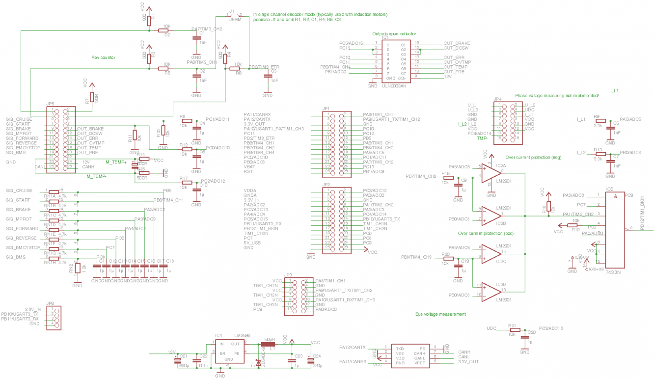
We're going a bit crazy here, so here's my version of OpenInverter hardware, homebrew etched. Some sections were changed - I used another PWM controller for resolver excitation, 3,5mm 'degsons' instead of proprietary connectors, different ESP8266 module etc. Overall it's based on mainboard v3.4 + leaf adapter. Seems to be working good right now, so we're ready to wire it up.
Thank you for any help in advance.
video_2023-11-13_16-56-45.mp4_snapshot_00.00.480.jpg
Cast in the name of God, ye not guilty.
User avatar
johu
Site Admin
Posts: 5789
Joined: Thu Nov 08, 2018 10:52 pm
Location: Kassel/Germany
Has thanked: 157 times
Been thanked: 1023 times
Contact:

Re: Gen2 IGBT Drivers board CNDR1 and CNDR2 pinouts

Post by johu »

That is so oldschool, nice :)

You can go back to the beginning, check the video description of this video it has some pinouts. Or just open leaf_adapter.fpc with a software called freepcb

Support R/D and forum on Patreon: https://patreon.com/openinverter - Subscribe on odysee: https://odysee.com/@openinverter:9
User avatar
SuppaTenko
Posts: 8
Joined: Mon Nov 13, 2023 1:40 pm
Contact:

Re: Gen2 IGBT Drivers board CNDR1 and CNDR2 pinouts

Post by SuppaTenko »

johu, thank you. But I asked about IGBT Drivers Board pinouts. Not about OpenInverter board.
As i said, I don't have stock cables. I can tell where all six PWM signals go, but I'm not sure about FAULT1, FAULT2, UDC_PWM, heatsink temp and both current sensors.
I'm talking about this board and sockets:
photo_2023-11-13_20-51-13.jpg
photo_2023-11-13_20-51-14.jpg
photo_2023-11-13_20-51-15.jpg
Cast in the name of God, ye not guilty.
User avatar
SuppaTenko
Posts: 8
Joined: Mon Nov 13, 2023 1:40 pm
Contact:

Re: Gen2 IGBT Drivers board CNDR1 and CNDR2 pinouts

Post by SuppaTenko »

Well... Should be something like this.
Please correct me if I'm wrong here.
Attachments
photo_3_2023-11-14_16-10-34.jpg
photo_3_2023-11-14_16-10-34.jpg (12.92 KiB) Viewed 2551 times
photo_2_2023-11-14_16-10-34.jpg
photo_2_2023-11-14_16-10-34.jpg (16.42 KiB) Viewed 2551 times
photo_1_2023-11-14_16-10-34.jpg
Cast in the name of God, ye not guilty.
User avatar
SuppaTenko
Posts: 8
Joined: Mon Nov 13, 2023 1:40 pm
Contact:

Re: Gen2 IGBT Drivers board CNDR1 and CNDR2 pinouts

Post by SuppaTenko »

Ok, we're definitely alive here. At least WIFI web-interface yields legit errors and numbers. Overall it consumes like 500-600 mAmps from 12V psu. Gonna test with engine and HV supply on upcoming Monday-Tuesday... Wish me luck! =)
Attachments
photo_2023-11-17_14-53-13.jpg
Cast in the name of God, ye not guilty.
User avatar
SuppaTenko
Posts: 8
Joined: Mon Nov 13, 2023 1:40 pm
Contact:

Re: Gen2 IGBT Drivers board CNDR1 and CNDR2 pinouts

Post by SuppaTenko »

Ok, we have an issue with both current sensors.
They show around ~2,45 volts on outputs with zero current - hapf supply voltage or so.
It's too much, should be between 1,23 and 2,06 vots. So we have permanent HICUROFS1/2 and OVERCURRENT stop.
Is it possible that our sensors are damaged?
Which sensors can be used as replacement?
Cast in the name of God, ye not guilty.
User avatar
johu
Site Admin
Posts: 5789
Joined: Thu Nov 08, 2018 10:52 pm
Location: Kassel/Germany
Has thanked: 157 times
Been thanked: 1023 times
Contact:

Re: Gen2 IGBT Drivers board CNDR1 and CNDR2 pinouts  [SOLVED]

Post by johu »

That's the voltage they should sit at. You need to divide it down to the 3V3 window, e.g. with 3k3/6k8 voltage divider
Support R/D and forum on Patreon: https://patreon.com/openinverter - Subscribe on odysee: https://odysee.com/@openinverter:9
User avatar
SuppaTenko
Posts: 8
Joined: Mon Nov 13, 2023 1:40 pm
Contact:

Re: Gen2 IGBT Drivers board CNDR1 and CNDR2 pinouts

Post by SuppaTenko »

johu, thx, will check input dividers tomorrow.
A bit confusing. We have 3k3+4k7 on mainboardv3.4.pdf from git, only 3k3 for v2 board wiki (https://openinverter.org/wiki/images/a/ ... ain_v2.png), mainboard_mini has 3k3+6k8 as you suggested and as far as I can remember, mine is 3k3+10k which is not enough.
Cast in the name of God, ye not guilty.
User avatar
SuppaTenko
Posts: 8
Joined: Mon Nov 13, 2023 1:40 pm
Contact:

Re: Gen2 IGBT Drivers board CNDR1 and CNDR2 pinouts

Post by SuppaTenko »

Ok. First, some problems with current sensors were solved. Now it calibrates just fine. Also, there were some strange shenanigans with protection circuit comparator and input/output logic. Also solved. Second, I found cross-layer short-circuit on IGBT board and restored and replaced everything damaged by high temperatures.
So, we had persistent precharge error, several strange overcurrents without any currents and HV, no stable calibration, i changed current sensor dividers etc, etc... Now we have no errors at all, which is good.

Now we can't properly calibrate resolver. I rolled back to FOC 4.97R FW. Angle indicator jumps between 150 and 340 deg. It doesn't mater if you rotate motor or not. The resolver (and engine) was not damaged by fire, so it's not the cause. 1,65V bias presents. We have nice cin/cos signals. But sin/cos waveforms seem to have low swing just around 500 mV (AFAIK, it should be close to 0...3v3 range - correct me if I'm wrong), and excitation waveform is too fuzzy.
My guesses are:
- bad TDA2822 - will check it this evening
- my TPS55340 booster provides wrong supply voltage for TDA amplifier.
According to my computations, MIC2288 should provide 1,24*(3300/510+1) = 9,26 volts with 510+3k3 divider. So does my TPS55340 with 10k+64k9 divider.
Can you show me excitation waveform parameters? What swing should it have? What output voltage your MIC2288 booster provides? Am I wrong?

Sorry for bad photo quality - pretty hard to test and film everything in process. It's excitation waveform and sin/cos outputs. Also, the bike =)
Also, please 'un-solve' this topic. We still have ways to go in this struggle =)
Attachments
video_2023-11-27_13-28-11.mp4_snapshot_01.04.727.jpg
video_2023-11-27_13-28-11.mp4_snapshot_00.40.950.jpg
video_2023-11-27_13-28-11.mp4_snapshot_00.37.954.jpg
video_2023-11-27_13-28-11.mp4_snapshot_00.26.967.jpg
video_2023-11-27_13-28-11.mp4_snapshot_00.18.976.jpg
photo_2023-11-24_21-46-10.jpg
Cast in the name of God, ye not guilty.
User avatar
SuppaTenko
Posts: 8
Joined: Mon Nov 13, 2023 1:40 pm
Contact:

Re: Gen2 IGBT Drivers board CNDR1 and CNDR2 pinouts

Post by SuppaTenko »

It was TDA. Now we have some spin. Time to tinker with resolver offset.

UPD. Got some decent RPMs and almost found good syncofs. But half-baked IGBTs finally decided to die. RIP.
Will wait for new inverter now. While it's been delivered I will apply some fixes to my logic board, also rework wires etc. And try to play with CAN bus control and something zombieverter-like in process.
Cast in the name of God, ye not guilty.
Post Reply