[DRIVING] 1975 Porsche 914 conversion restoration and modernizing

Tell us about the project you do with the open inverter
Post Reply
User avatar
nickyivyca
Posts: 15
Joined: Thu Jul 06, 2023 4:45 pm
Location: California
Has thanked: 2 times
Been thanked: 8 times

[DRIVING] 1975 Porsche 914 conversion restoration and modernizing

Post by nickyivyca »

This was originally converted over 10 years ago by the previous owner:
http://www.evalbum.com/2784
http://cruzware.com/peter/blog
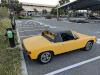
Back when I was in college at UC Santa Cruz, I was a founding member of the FSAE Electric team there, Formula Slug. Peter the previous owner donated the car to the team and it ended up in my care. There were no batteries, but if I hooked up a high voltage power supply to where the battery + and - used to be and keyed on, I could spin the motor, so the car was mostly functional just needed a battery to get rolling again. The wiring in the back could use some touching up - high voltage was a bit exposed. The motor and inverter were from a company I had never heard of called Greatland Electric - if you search up the part numbers on that page, all you get is the motor in my car. The previous owner gave me a datasheet which had some useful information but not a whole lot. There was no communication interface that worked - it had CAN pins but nothing was on the bus no matter what speed I set, and no (documented) configuration interface either. The motor is mounted to the original transmission through a clutch, supposedly is capable of 250Nm, was RPM limited to 4000RPM with the existing controller, and limited to 80kW or so.

Other than picking up some batteries for it, I didn't really get to working on it until the pandemic struck, when I told myself I could get it running before society "resumed" again - so I set out to do that.

First step was to get the battery pack going. The batteries I had were 28s 29ah Farasis modules - the same as used in Zero Motorcycles. But, I had no BMS for them. The year after I graduated the FSAE team had built up their own BMS using LTC6811 chips over IsoSPI, and wrote the software. So I made my own BMS using the related LTC6813 chips, and used the Formula Slug software library to communicate with them. I was able to use this to spin up the motor and drive the car around a bit, around late February 2021. You can see the exposed main pack fuse here - there are some less obvious things that needed fixing as well. I was able to put the batteries in the original Electro Automotive battery box that the old iron phosphate cells were in before, which was quite handy.
IMG_20210131_210441.jpg
Next up, charging. The car came with a Manzanita Micro charger - many of the old EV conversions I've seen have them, it's the green box in the above photo. It didn't seem to work when I tried it, so I contacted the original manufacturer. Turns out, it will overvolt and fry itself if you power it on without a battery connected. So, I mailed mine in to be fixed, got it back, hooked it up to charge for a bit, it seemed to work but the current output was a bit spiky. I then opened my battery contactors, plugged it in again, and fried it again. So, I decided it was time for a better and more modern charger, preferably with built in J1772 negotiation. This is when I really first discovered openinverter and the Tesla Gen2 charger - got my hands on one from Ebay and a kit from the shop, was able to get it set up and running and start J1772 charging pretty easily. The main things that tripped me up were needing to desolder the connector from the Tesla board (this was peak supply chain shortages) and needing to set up the CAN termination.
IMG_20210611_201910.jpg

I also set up a real high voltage junction box at this point to reduce the chances of death or at least dropped wrenches wreaking havoc, and to give the charger contactor a place to be.
IMG_20210405_210641.jpg
Once I fixed the sound system, getting the subwoofer working (very important) and added a display for battery voltages, pack current, and a power bar (top line of the display) the car was driveable. This was June 2021 or so, so I had basically accomplished my goal! I started just driving it as much as I could. Found out it had about 30 miles of range with the 7.5kwH or so the 3 Farasis modules had in them, which wasn't much but was enough. The controller did some regen but really not much - only up to 15ADC and only below 2000rpm. The motor was definitely plenty to get the car moving, the battery was definitely still the limiting factor - 80kW on these batteries can be nearly 10C, so you could only really do that for a second or two before it wasn't a good idea. But, was still able to chirp the tires a bit in second gear.


Next up was a sort of combo VCU/contactor control board. I had been running on a breadboard hanging out by my feet talking over IsoSPI and driving a little display in the dash, so I built that as well as contactor control, some 12V GPIOs for various outputs for the lights on the dash, etc into a PCB and installed that into the car. I was able to write up an SoC estimator and use that to drive the fuel gauge in the dash, as well as light up some of the LEDs for various faults (including the low 'fuel'/reserve light set for 15% SoC or below). I also set up a CAN interface on here for once I replaced the inverter so I could use data from it to drive the tachometer or send commands/limits to it from the BMS software.
image.png
PXL_20230717_035758379.jpg
PXL_20230717_015207879.jpg
Next up was better batteries. I was able to get ahold of some fresher 32ah modules of the same form factor - the 29ahs were well used. I was able to swap these in for the original 3 pretty easily. I then set about building a second set to go in the front, they fit pretty much perfectly in the Electro Automotive battery box that took the space that the fuel tank used to occupy. I have no plans to fill the frunk with batteries - it's great to have that space.
PXL_20220907_0210157800.jpg
This allowed me to finally really put the pedal down and try to reach that real 80kW target. This is when I found that sometimes, you end up doing a 'clutch burnout'...you can hear the RPMs surge in this video when it happens. Generally it didn't happen though. With the 4000RPM limit and the gearing, 2nd gear only got you to 30mph (quite quickly though) so 3rd -> 4th was usually how I would pull onto the highway.


At this point the car was pretty sweet so I just started driving it around more. With 6 of the Farasis modules this got me about 18kWhr or so, which gave me about 70 miles of range, consumption was 210-240wh/mile depending on various factors (out of the battery, not including charger losses). For example, this was after about a 35 mile mostly 50-60mph drive starting at 4.15v/cell or so.
PXL_20230614_173738011.jpg
But, the existing inverter was now the limiting factor of the car. The motor itself was fine - torquey, and I figured with a new inverter I could actually configure I could get a higher top speed out of it. After some investigating it became pretty clear that a Leaf inverter with the openinverter control board was the best option, so I bought one off Ebay and the kit from the shop. The inverter arrived with the busbars a bit busted up, which I figured wasn't an issue, until I opened it up (voiding any chance of returns) and found that the PCB and one of the modules was cracked. So I basically bought some spare inverter parts for $500. It did allow me to start figuring out how the inverter would fit in the car, and allowed me to get ahead on desoldering the unobtanium connector. The resolver interface on the openinverter board with one pin of sin and cos tied together is also perfect for me - since the resolver in the Greatland Electric motor somehow only has 5 wires coming out of it, sin and cos have a common somewhere within its windings.
PXL_20230408_220509890.jpg
I then bought a whole Leaf gen2 drive unit from a junkyard - $1100 USD for the whole stack. I figure if I ever want to swap out the Greatland Electric motor for the Leaf motor I could just use the original control board and CAN control since I hadn't modified its matched control board. Also, it came in handy for bringup of the Leaf inverter, figuring out the intricacies of using it using the OEM harness and known motor control constants, before I tried using it with a motor that nobody else in the (Western) world seems to be aware of. I ended up having to set pinswap to 6 which it wasn't at originally - curious if anyone else had to do this for their Leaf inverters.

Just in the past week or so I finished integrating the Leaf inverter into the car. I ended up trimming one of the DC input busbars so I could have the cables exit sideways, and 3d printed shrouds for the DC input and phase output. Some initial guesses about motor control constants later and I had the motor spinning, and once I had corrected my reversed resolver constant (resulting in flux strengthening instead of flux weakening - thanks Pete), I was off and running. I drove the car around a bit honing in on some initial guesses of flux level and lqminusld which seem to be performing pretty well, still more tuning to do but I'm fairly close to where I was with the Greatland Electric inverter, except with much better regen, the higher redline I had always wanted of 5600 (matching the 914's original redline). It still feels a bit power limited, but I figure with some better tuning, perhaps running the log based parameter estimator I'll be able to get some better performance. Still very happy with how the openinverter Leaf inverter worked out - I figure any off the shelf inverter would've been more expensive and tougher to set up with a motor that came with no parameters. And now I finally have a functional tachometer.
PXL_20230717_015108795.jpg


What's next? In rough order...
  • Optimize motor controls and raise power level - to the point I need to set up a power limit
  • Swap throttle pedal (I have one of the BMW pedals already, just needed to get the new inverter in first)
  • Either a knob to control regen level, or a sensor to blend with the regular brakes (Anyone have any tips as to which of these are better?)
  • Third set of Farasis modules
Here are the github repos for my control board software and the ltc BMS chip library, I'll post more details about the BMS boards and what's going on in my software soon.
https://github.com/nickyivyca/914-control
https://github.com/nickyivyca/lib-mbed-ltc681x
User avatar
nickyivyca
Posts: 15
Joined: Thu Jul 06, 2023 4:45 pm
Location: California
Has thanked: 2 times
Been thanked: 8 times

Re: 1975 Porsche 914 conversion restoration and modernizing

Post by nickyivyca »

Latest update: thanks to Pete's motor parameter estimator, was able to make some tuning improvements to the motor, such that I can get a bit better performance out of it. Even with a fairly empty battery I get pretty close to 80kW. Increasing max flux weakening current to 700A also helped - I was worried that setting 700A would actually result in 700A being used, since 700A is my overcurrent limit, but then I realized after reading the parameter description page that this is the theoretical maximum flux weakening current (if you gave it this much the flux would be completely eliminated) and I should never see 700a.


Though I think in general I won't really be able to get much more out of this motor - It supposedly makes around 250Nm. This means I need to be at just over 3000rpm to actually be making around 80kW. However, the motor starts needing flux weakening at around that speed given my battery voltage, taking current away from making torque. So I am effectively limited to ~80kW unless I increase my phase current/torque, which I don't want to do given how old this transmission is, and the clutch can already be a limiting factor depending on its mood. With the increased max RPM, it's still a performance upgrade over what I had before, and still plenty of power for the car.

Some other design details...

Here are the block diagrams. Each battery string gets its own contactors and fuse, which are colocated with each battery string. That way when the car is off HV only remains within the battery box enclosures. Low side fuse on the front was done mostly for packaging reasons, but even if front battery's positive lead gets shorted to rear battery's negative lead, the fuses still protect since they are in series. I use slow-blow fuses on the battery strings to protect them and the wiring (using a mix of 4awg and 6awg on the battery strings), while separately the main fuse is a fast-blow to blow quickly if there's ever an inverter side issue, but still also protecting the 2/0 leads from HV box to inverter.
914-HV System.drawio.png
914-LV System.drawio.png
The PP75 connectors allow me to swap in a regular extension cable there for charging without an EVSE.

On the LV side, there are 2 ways to power on the car - through the normal ignition key, and also through a switch located next to the charging port. This allows me to have the car powered on while charging it without leaving the key in, and also gives the vehicle control board notice that the car is in charging mode, so it can respond accordingly, sending charge enable and enabling balance resistors if everything is healthy, plus disabling the inverter.
The DCDC (MeanWell HEP-320-15A, a bit underpowered but is enough for my needs) and the rear fusebox share a relay that isolates them from the main 12v battery, both serving to turn off the components on the rear fusebox when the car is off, and also preventing any parasitics in the DCDC from draining the battery down.

The vehicle control board controls the main battery contactors - when the car first starts up, it checks the battery voltages to make sure that both strings are healthy and also that they are similar in voltage (don't want to close the battery contactors between unmatched battery strings). Before the contactor power goes off to each battery box, it goes through a switch on the dash and also a crash switch - the switch on the dash acts as a sort of e-stop, while the crash switch allows the contactors to automatically open if the car gets in a crash.


As for my cellbox BMS, I can't share the schematics or layout of the BMS boards since they may contain proprietary information about the cellboxes. But, it's basically a datasheet implementation of 2 6813s, each measuring half the cells, the top measuring a current sensor and the bottom measuring the 2 NTCs in the battery box (to keep them referenced to B-). They are connected to the analog channels 1 and 2 on each chip, this way I can use the ADCVAX command to read all cell voltages, the current, and the temperatures all in one go. I have transformer isolation on the outputs of each board and then capacitive isolation between the 2 chips on each board. Shielded twisted pair cable connects each of the cellboxes in the string and to the vehicle control board.

Making the BMS boards took a while but was doable - I had access to a reflow oven and ordered stencils with my boards, but manually picking and placing all those little components took a while. But, on early boards I did have issues with corrosion given these boards spend all of their time with voltage on them. I ended up having to conformal coat the base of the pins that interface with the battery box itself (the front battery boxes I completely conformal coated for good measure) and also had some of my earlier boards develop shorts over time between the chassis and battery regions, on later revisions I added more clearance in this area.

I will share schematics/layout for my vehicle control board once I've updated it and fixed all of the many bugs in it, don't want to give anyone any wrong ideas...The LPC1768 microcontroller I'm using on it now with mbed framework works fairly well, but I have no need for Ethernet and I want more GPIOs, so I'm likely switching to a Nucleo-G474RE so I can get rid of the I2C IO expander.

Now that I've sort of accomplished my first bullet point above, next up is the throttle pedal upgrade. I was going to dig into increasing the regen while I'm in there, but I have realized when driving the car around that even the small-ish amount of regen I get (up to 15kWish, limited by 1C battery charge limit) is still plenty of regen such that on the hills I mainly drive on, I still don't use much friction brakes, so there's not much more energy to be gained by increasing it, might not be worth the effort/added complexity.
User avatar
johu
Site Admin
Posts: 5791
Joined: Thu Nov 08, 2018 10:52 pm
Location: Kassel/Germany
Has thanked: 157 times
Been thanked: 1025 times
Contact:

Re: 1975 Porsche 914 conversion restoration and modernizing

Post by johu »

Nice, thanks for the detailed writeup.

On Audi I use an AC coil relay to power the car as soon as AC voltage enters the charge port.
Touran uses PP signal for partly powering up
Support R/D and forum on Patreon: https://patreon.com/openinverter - Subscribe on odysee: https://odysee.com/@openinverter:9
Post Reply