Field oriented control of induction motors
-
Pete9008
- Posts: 1801
- Joined: Sun Apr 03, 2022 1:57 pm
- Has thanked: 102 times
- Been thanked: 350 times
Re: Direct current control of induction motors
I think it might be reformulating it as a transfer function but afraid I was never much good at those and even that minimal understanding seems a long time ago 
-
catphish

- Posts: 961
- Joined: Fri Oct 08, 2021 11:02 pm
- Location: Dorset, UK
- Has thanked: 98 times
- Been thanked: 195 times
-
johu

- Site Admin
- Posts: 6748
- Joined: Thu Nov 08, 2018 10:52 pm
- Location: Kassel/Germany
- Has thanked: 380 times
- Been thanked: 1571 times
- Contact:
Re: Direct current control of induction motors
Probably a bit late to the party but I remember way back I had applied Park/Clark in my Polo to calculate active, reactive and apparent power. It seems I was successful in doing so as this plot denotes:
The file is dated 13/3/2014
I remember I just used motor angle + slip angle for the transforms.
I can't find the source code at the point in time. It must be somewhere here: https://github.com/tumanako/tumanako-in ... 2_sine.cpp (back then the control code still resided in the main file). Will keep looking, maybe it somehow helps.
EDIT: found it, it was done in the 1Ms task
https://github.com/tumanako/tumanako-in ... e.cpp#L301
Support R/D and forum on Patreon: https://patreon.com/openinverter - Subscribe on odysee: https://odysee.com/@openinverter:9
-
catphish
- Posts: 961
- Joined: Fri Oct 08, 2021 11:02 pm
- Location: Dorset, UK
- Has thanked: 98 times
- Been thanked: 195 times
Re: Direct current control of induction motors
Good results there, looks a lot like some of my plots of transient states.johu wrote: ↑Sat Feb 11, 2023 5:23 pm Probably a bit late to the party but I remember way back I had applied Park/Clark in my Polo to calculate active, reactive and apparent power. It seems I was successful in doing so as this plot denotes:
power.png
The file is dated 13/3/2014
I remember I just used motor angle + slip angle for the transforms.
I can't find the source code at the point in time. It must be somewhere here: https://github.com/tumanako/tumanako-in ... 2_sine.cpp (back then the control code still resided in the main file). Will keep looking, maybe it somehow helps.
EDIT: found it, it was done in the 1Ms task
https://github.com/tumanako/tumanako-in ... e.cpp#L301
The code is basically the same as mine (though your library has improved and made it easier for me): https://github.com/catphish/stm32-sine/ ... L188..L192
Also worth noting - you knew how to calculate Is (ilmax) all along, although I guess doing it this way is a bit expensive compared to my hypot3 method.
-
johu
- Site Admin
- Posts: 6748
- Joined: Thu Nov 08, 2018 10:52 pm
- Location: Kassel/Germany
- Has thanked: 380 times
- Been thanked: 1571 times
- Contact:
Re: Direct current control of induction motors
Indeed. I think the need to feed il1 and il3 to the transforms must be down to the current sensors not actually being on L1 and L2. The FOC code uses "pinswap" to correct for this.
EDIT: oh yes, Prius Gen2 indeed has sensors on L1 and L3 if I remember correctly. Implication: what works on your bench will not work on your Tesla SDU.
EDIT: oh yes, Prius Gen2 indeed has sensors on L1 and L3 if I remember correctly. Implication: what works on your bench will not work on your Tesla SDU.
Support R/D and forum on Patreon: https://patreon.com/openinverter - Subscribe on odysee: https://odysee.com/@openinverter:9
-
catphish
- Posts: 961
- Joined: Fri Oct 08, 2021 11:02 pm
- Location: Dorset, UK
- Has thanked: 98 times
- Been thanked: 195 times
Re: Direct current control of induction motors
Yep, I got to the bottom of this. The Prius Gen2 current sensors are L2 and L3.johu wrote: ↑Sat Feb 11, 2023 5:38 pm Indeed. I think the need to feed il1 and il3 to the transforms must be down to the current sensors not actually being on L1 and L2. The FOC code uses "pinswap" to correct for this.
EDIT: oh yes, Prius Gen2 indeed has sensors on L1 and L3 if I remember correctly. Implication: what works on your bench will not work on your Tesla SDU.
The Tesla SDU is *negative* L1 and L2.
Edit: the reason I use L1 and L3 is not because of the current sensor mapping, that's done further up, but because the direction is reversed. The sine code drives the motor backwards. (L3 then L2 then L1).
Edit2: Heres why:
Code: Select all
    sine[0] = SineLookup(angle);
    sine[1] = SineLookup((angle + PHASE_SHIFT120) & 0xFFFF);
    sine[2] = SineLookup((angle + PHASE_SHIFT240) & 0xFFFF);
-
catphish
- Posts: 961
- Joined: Fri Oct 08, 2021 11:02 pm
- Location: Dorset, UK
- Has thanked: 98 times
- Been thanked: 195 times
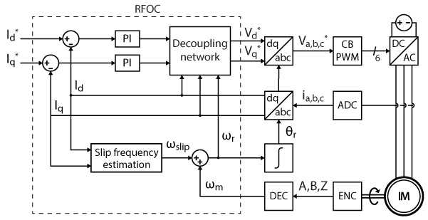
Field oriented control of induction motors
Here's what I'm thinking so far, based on the formulas at https://imperix.com/doc/implementation/ ... ed-control
Lots of work to do to determine the correct constants for my motor, and of course the actual PIDs, which I might be able to delegate to the FOC module, but I worry it might contain black magic that doesn't apply to my motor.
This is just float based pseudocode for now, but I should be able to add this to the FOC module as fixed point code.
Note: I'm also renaming this thread to reflect the fact that it's basically about FOC and not what it was originally supposed to be about.
Note2. This in no way detracts from my current control branch, which is working beautifully in my car, but which I guess won't replace the V/Hz sine version, since it has no regen.
Code: Select all
// LM is a constant based on the properties of the motor
#define LM 1.0f
// TR is a constant based on the properties of the motor but also the 4.4kHz callback frequency
#define TR 1.0f

   // Calculate IQ and ID
   FOC::SetAngle(angle);
   FOC::ParkClarke(il1, il2);
   Param::SetFixed(Param::iq, FOC::iq);
   Param::SetFixed(Param::id, FOC::id);

   // Calculate rotor flux magnitude
   static float rotorFlux = 0;
   rotorFlux -= rotorFlux / TR;
   rotorFlux += FOC::id * LM / TR;
   // Calculate slip speed
   slipIncr = FOC::iq * LM / TR / rotorFlux;
This is just float based pseudocode for now, but I should be able to add this to the FOC module as fixed point code.
Note: I'm also renaming this thread to reflect the fact that it's basically about FOC and not what it was originally supposed to be about.
Note2. This in no way detracts from my current control branch, which is working beautifully in my car, but which I guess won't replace the V/Hz sine version, since it has no regen.
-
Pete9008
- Posts: 1801
- Joined: Sun Apr 03, 2022 1:57 pm
- Has thanked: 102 times
- Been thanked: 350 times
Re: Field oriented control of induction motors
Is that the complete pseudocode - it looks too simple??
-
catphish
- Posts: 961
- Joined: Fri Oct 08, 2021 11:02 pm
- Location: Dorset, UK
- Has thanked: 98 times
- Been thanked: 195 times
Re: Field oriented control of induction motors
Yes
I agree, it does seem excessively simple. I could well be missing something. This is based on the paper I linked yesterday.
It's also now not too dissimilar to this earlier attempt: https://github.com/tumanako/tumanako-in ... ngle.c#L69
-
Pete9008
- Posts: 1801
- Joined: Sun Apr 03, 2022 1:57 pm
- Has thanked: 102 times
- Been thanked: 350 times
Re: Field oriented control of induction motors
Wow!
Afraid I've not gone through that paper in great detail (brain doesn't want to work today) but it would be great if it did simplify down to something like that. Fingers crossed!
Afraid I've not gone through that paper in great detail (brain doesn't want to work today) but it would be great if it did simplify down to something like that. Fingers crossed!
-
catphish
- Posts: 961
- Joined: Fri Oct 08, 2021 11:02 pm
- Location: Dorset, UK
- Has thanked: 98 times
- Been thanked: 195 times
Re: Field oriented control of induction motors
It would be great if you were able to read it at some point and tell me if what I'm doing seems sane. Of course no pressure! It's been hard to find people who understand this well, so I really appreciate your help so far! I'll press ahead in the next couple of days hopefully.
-
catphish
- Posts: 961
- Joined: Fri Oct 08, 2021 11:02 pm
- Location: Dorset, UK
- Has thanked: 98 times
- Been thanked: 195 times
Re: Field oriented control of induction motors
An interesting implication of this concept is that because it takes time to magnetize the rotor, one ideally wants to keep it consistently magnetized at all times (ie maintain constant D-axis current, and end up with an approximation of a PM motor). This makes a lot of sense when moving, but becomes a little bit silly when stationary, you'd just be feeding a DC current.
Obviously in a PM motor, the field is already there, so it's sufficient to maintain the D axis current at zero most of the time.
My current control firmware actually used to do exactly this, applying a minimum current at all times, but I removed the option because I realised it's way too easy to damage some inverters if they're turned off while current is flowing (ie stopped but left in gear).
Now getting ahead of myself a little, it seems to me that during normal driving, we'll need to compensate for this gradual increase in rotor field at startup, but might be fun to add a launch control button to activate 100% D-current in advance (at DC) to allow instant full torque.
-
Pete9008
- Posts: 1801
- Joined: Sun Apr 03, 2022 1:57 pm
- Has thanked: 102 times
- Been thanked: 350 times
Re: Field oriented control of induction motors
I think I agree with that with one small change (kind of already implied but just to be clear):catphish wrote: ↑Sat Feb 11, 2023 6:59 pm Here's what I'm thinking so far, based on the formulas at https://imperix.com/doc/implementation/ ... ed-control
Lots of work to do to determine the correct constants for my motor, and of course the actual PIDs, which I might be able to delegate to the FOC module, but I worry it might contain black magic that doesn't apply to my motor.Code: Select all
// LM is a constant based on the properties of the motor
#define LM 1.0f
// TR is a constant based on the properties of the motor but also the 4.4kHz callback frequency
#define TR 1.0f

   // Calculate IQ and ID
   FOC::SetAngle(angle);
   FOC::ParkClarke(il1, il2);
   Param::SetFixed(Param::iq, FOC::iq);
   Param::SetFixed(Param::id, FOC::id);

   // Calculate rotor flux magnitude
   static float rotorFlux = 0;
   rotorFlux -= rotorFlux / TR;
   rotorFlux += FOC::id * LM / TR;
   // Calculate slip speed
   slipIncr = FOC::iq * LM / TR / rotorFlux;
This is just float based pseudocode for now, but I should be able to add this to the FOC module as fixed point code.
Note: I'm also renaming this thread to reflect the fact that it's basically about FOC and not what it was originally supposed to be about.
Note2. This in no way detracts from my current control branch, which is working beautifully in my car, but which I guess won't replace the V/Hz sine version, since it has no regen.
Code: Select all
// LM is a constant based on the properties of the motor
#define LM 1.0f
// TR is a constant based on the properties of the motor but also the 4.4kHz callback frequency
#define TR 1.0f
static float rotorFlux = 0;

main_loop()
{
   // Calculate IQ and ID
   FOC::SetAngle(angle);
   FOC::ParkClarke(il1, il2);
   Param::SetFixed(Param::iq, FOC::iq);
   Param::SetFixed(Param::id, FOC::id);

   // Calculate rotor flux magnitude
   rotorFlux -= rotorFlux / TR;
   rotorFlux += FOC::id * LM / TR;
   // Calculate slip speed
   slipIncr = FOC::iq * LM / TR / rotorFlux;
Ended up ignoring equation 26 and working from equation 9.
The bit that is still confusing me is that this calculation is based on already having Iq and Iq which relies on already having the RRF worked out, bit chicken and egg. Assume the idea is that you start from the stationary known state and track them but that is prone to cumulative error. Some papers seem to talk about a feedback loop based on comparing calculated to measured BEMF, guessing that is to minimise this??
Like the idea of the launch control button BTW - wonder if that is what Tesla's Ludicrous mode does??
Edit - ignore comment about the change above, that's what the static keyword does inside a function. I don't tend to use it like that so had to look it up!
-
Pete9008
- Posts: 1801
- Joined: Sun Apr 03, 2022 1:57 pm
- Has thanked: 102 times
- Been thanked: 350 times
Re: Field oriented control of induction motors
Just found the definition of Tr (to the right of equation 8) = Lr/Rr so it's essentially the natural decay of the rotor field due to rotor resistance.
That all makes sense then, equation 9 is essentially comparing the energy added to the energy lost in each delta t, the difference being proportional to the rate of change of flux
That all makes sense then, equation 9 is essentially comparing the energy added to the energy lost in each delta t, the difference being proportional to the rate of change of flux
-
catphish
- Posts: 961
- Joined: Fri Oct 08, 2021 11:02 pm
- Location: Dorset, UK
- Has thanked: 98 times
- Been thanked: 195 times
Re: Field oriented control of induction motors
I really like using "static" ie local but persistent variables like this. It avoids polluting the wider application with class level or global scope variables when they're only used in a single function. This is particularly true during development, where it's much easier to create a static local variable rather than having to go and define them at a class level.
Yeah I never got my head around equation 26. My implementation of flux angle is based exclusively on equations 9 and 27.
This may not be as much of a problem as it seems for three reasons:Pete9008 wrote: ↑Sun Feb 12, 2023 1:51 pm The bit that is still confusing me is that this calculation is based on already having Iq and Iq which relies on already having the RRF worked out, bit chicken and egg. Assume the idea is that you start from the stationary known state and track them but that is prone to cumulative error.
1) Starting from the motor being completely de-energized, the orientation doesn't matter. The orientation will begin at whatever angle we first start injecting current.
2) The flux magnitude, while integrated, converges to a constant multiple of Id (see equation 11).
3) The orientation is clearly prone to error here, but I don't believe it's possible for this error to accumulate. Any error we make in calculating slip speed will result in a matching change in actual slip speed. Our D and Q currents will no longer be what we think they are, but the error will be consistent, not cumulative.
One thing to note is that most people actually seems to use *commanded* rather than measured Id and Iq for their slip estimation. I guess it's more stable and near enough the same value. Though this paper seems to use the measured values, and so does my proposed implementation for now.
Edit: be aware, my mindless optimism may evaporate when I try running this on an actual motor and not just in my head!
-
Pete9008
- Posts: 1801
- Joined: Sun Apr 03, 2022 1:57 pm
- Has thanked: 102 times
- Been thanked: 350 times
Re: Field oriented control of induction motors
The trouble is I don't tend to code enough these days to develop new habits and if I try it just tends to lead to errors. I also tend to speed read so have a habit of seeing what I think is there rather than what is actually there, sticking to a specific style of code tends to help with this. If I see a variable defined inside a function I automatically treat it as having a limited lifetime, hence my original comment. Similarly I know when using == I should have the constant on the left but just find it incredibly difficult to read code done that way round! I've accepted that my code is never likely to be elegant, I'm just happy if it works!catphish wrote: ↑Sun Feb 12, 2023 5:12 pm I really like using "static" ie local but persistent variables like this. It avoids polluting the wider application with class level or global scope variables when they're only used in a single function. This is particularly true during development, where it's much easier to create a static local variable rather than having to go and define them at a class level.
In theory yes, in practise integrators always seem to cause me problems, hope you have better luck with this one
Edit - forgot to say you will need to scale the Tr definition above by the control loop execution frequency.
-
catphish
- Posts: 961
- Joined: Fri Oct 08, 2021 11:02 pm
- Location: Dorset, UK
- Has thanked: 98 times
- Been thanked: 195 times
Re: Field oriented control of induction motors
It would appear that LM actually cancels out and we only need one constant!
should be equivilent to
...right?
Code: Select all
   // Calculate rotor flux magnitude
   rotorFlux -= rotorFlux / TR;
   rotorFlux += FOC::id * LM / TR;
   // Calculate slip speed
   slipIncr = FOC::iq * LM / TR / rotorFlux;
Code: Select all
   // Calculate rotor flux magnitude
   rotorFlux -= rotorFlux / TR;
   rotorFlux += FOC::id / TR;
   // Calculate slip speed
   slipIncr = FOC::iq / TR / rotorFlux;
-
Pete9008
- Posts: 1801
- Joined: Sun Apr 03, 2022 1:57 pm
- Has thanked: 102 times
- Been thanked: 350 times
Re: Field oriented control of induction motors
Don't think so, Lr is only in the first term (-= one) not both so won't cancel?
-
catphish
- Posts: 961
- Joined: Fri Oct 08, 2021 11:02 pm
- Location: Dorset, UK
- Has thanked: 98 times
- Been thanked: 195 times
Re: Field oriented control of induction motors
I decided it should cancel and removed it. The only places it appears are as a constant multiplier of Id and Iq. It could therefore be described as the unit "Amps" which is cancelled out in the final calculation.
Anyway... proposed code. Not yet tested!
https://github.com/catphish/stm32-sine/ ... 07ac931d26
Going back over the code, I feel like this might work in steady state, but there's one aspect that concerns me. During startup, the rotor flux starts at zero, which means the slip frequency is infinite. While that might be mathematically correct, I don't yet understand how it can be magnetized from such an absurd starting state.
-
Pete9008
- Posts: 1801
- Joined: Sun Apr 03, 2022 1:57 pm
- Has thanked: 102 times
- Been thanked: 350 times
Re: Field oriented control of induction motors
Need to write it out to be sure but if the rotorFlux calculation is written on a single line rather than two them Lm isn't common to both terms and so won't cancel when calculating slip. Or am I misunderstanding the question?
-
catphish
- Posts: 961
- Joined: Fri Oct 08, 2021 11:02 pm
- Location: Dorset, UK
- Has thanked: 98 times
- Been thanked: 195 times
Re: Field oriented control of induction motors
I'm not sure how best to explain, but I'm thinking that Lm multiplies the input value FOC::id, and hence comes along with it throughout the recursive process. Perhaps this is clearer if written like this:
Code: Select all
   IdLm = FOC::id * LM;
   rotorFlux -= rotorFlux / TR;
   rotorFlux += IdLm / TR;
-
Pete9008
- Posts: 1801
- Joined: Sun Apr 03, 2022 1:57 pm
- Has thanked: 102 times
- Been thanked: 350 times
Re: Field oriented control of induction motors
If you look at equation 10 it makes more sense. Starting from zero Iq will also be zero so the equation balances. When volts are applied Iq will start to increase but will do so slowly because of Lm, as it increases the induced current into the rotor causes the flux to rise in sync with it. (I think?!?)
Edit - replies crossed, this is in response to previous post!
Edit - replies crossed, this is in response to previous post!
-
Pete9008
- Posts: 1801
- Joined: Sun Apr 03, 2022 1:57 pm
- Has thanked: 102 times
- Been thanked: 350 times
Re: Field oriented control of induction motors
Going to have to get a bit of thinking paper and write it out long hand, but not tonight! Afraid I can't 'see' it when written out like that.catphish wrote: ↑Sun Feb 12, 2023 10:30 pm I'm not sure how best to explain, but I'm thinking that Lm multiplies the input value FOC::id, and hence comes along with it throughout the recursive process. Perhaps this is clearer if written like this:
All terms just become LM larger.Code: Select all
   IdLm = FOC::id * LM;
   rotorFlux -= rotorFlux / TR;
   rotorFlux += IdLm / TR;
-
catphish
- Posts: 961
- Joined: Fri Oct 08, 2021 11:02 pm
- Location: Dorset, UK
- Has thanked: 98 times
- Been thanked: 195 times
Re: Field oriented control of induction motors
Studying FOC has lead me to notice a fairly obvious problem in the Id / Iq calculation I did previously. Because the same angle is used for the Park/Clarke and for the fixed (100% Uq) voltage output, it assumes that the Q axis is aligned with the voltage output. This is of course a hugely incorrect assumption.catphish wrote: ↑Sun Feb 12, 2023 9:47 pm Anyway... proposed code. Not yet tested!
https://github.com/catphish/stm32-sine/ ... 07ac931d26
Going back over the code, I feel like this might work in steady state, but there's one aspect that concerns me. During startup, the rotor flux starts at zero, which means the slip frequency is infinite. While that might be mathematically correct, I don't yet understand how it can be magnetized from such an absurd starting state.
Hopefully I can get a very simple FOC algorithm up and running (likely using a fixed d-axis current target, assuming steady flux magnitude). This should allow me to collect some better data.