OK. I've got it about inverter is active despite "STR" pin is not activated. Stupid me, I believed that picture on wiki, that is 50% wrong. I've just connected inverter shutdown pin to 12 volts....=( So why there is a "STR" pin in a first place? What is it doing, except shutting down precharge contactor?
Can please someone tell me if this board is compatible with latest sine firmware? Or it is not because bluepill pins are different from those STM32 chips on latest boards? If so, which version of sine is compatible with bluepill?
Toyota Prius Gen 2 Inverter Controller
-
konstantin8818

- Posts: 287
- Joined: Sun Jan 19, 2020 2:33 pm
- Location: Minsk, Belarus
- Been thanked: 5 times
-
MattsAwesomeStuff
- Posts: 898
- Joined: Fri Apr 26, 2019 5:40 pm
- Has thanked: 291 times
- Been thanked: 177 times
Re: Toyota Prius Gen 2 Inverter Controller
It's a collaborative effort. The pic was based on the assumptions of someone who had no idea what they were doing (me).Stupid me, I believed that picture on wiki, that is 50% wrong.
I created it by what my first guess was as to how to connect what to what, since there wasn't documentation, and when I first posted it I said: "4 - I'm not sure I've connected all my driving components correctly (Throttle, Brake, Brake Switch, Start, Forward, Reverse, Motor Temp, Heat Temp), I presume these are just tied to ground, not the other way and tied to the positive rail?"
Keep in mind this was written by someone who at first presumed the unspec'd diode on the control board would need to be rated for full current and voltage of the pack. I don't know what I'm doing and I make lots of mistakes.
My goal was to document what everyone else told me so that at least if I was being annoying by asking a million questions, not being able to figure things out on my own, and requiring everyone to hold me hand every step of the way... that at least I would be the *only* person who they had to do that to because thereafter the wiki would be complete enough to use as a reference.
No one ever corrected me, and I haven't worked on my inverter in 4 or 5 months.
So, yeah. If you have a complete list of changes needing to be made, make them and I'll update the picture. I've just been waiting since the last time you mentioned this, to figure out all the bugs before I redrew it.
It does look like that despite there being two much better, finished solutions (Gen 3 from EVBMW and Gen 2 from OpenInverter), people are still keen on the lowest cost solution (~$100) rather than a polished one (at ~$500). Which I suppose makes sense, because the Gen 2 especially was highlighted as the budget way for a novice to get a motor spinning and is still attractive as such. Maybe this design will have longer legs than intended.
Regardless, it's helpful to for everyone to know how to hook it up to their car hardware. I know that lots of novices came to this thread, got this hardware, and are hoping to be able to follow a procedure to get to a working EV. In particular because of how dumbed-down this thread is to their (myself included) knowledge level.
-
konstantin8818
- Posts: 287
- Joined: Sun Jan 19, 2020 2:33 pm
- Location: Minsk, Belarus
- Been thanked: 5 times
Re: Toyota Prius Gen 2 Inverter Controller
At that moment I didn't knew it was an effort, but not the picture from Damien himself as an author of the board. Comlete realisation of how things work here came to my mind not so lond ago, yes I'm a little slow pacedMattsAwesomeStuff wrote: ↑Sun Jun 28, 2020 12:35 am It's a collaborative effort. The pic was based on the assumptions of someone who had no idea what they were doing (me).
I didn't tried to blame anybody, I was blaming myself for blind belief.
Now I could update this picture but there are still some issues with the board, such as direction select works incorrect, main contactor is not closing, and wiki page is thrown somevhere, I can't find it.
-
Jack Bauer

- Posts: 3563
- Joined: Wed Dec 12, 2018 5:24 pm
- Location: Ireland
- Has thanked: 1 time
- Been thanked: 87 times
- Contact:
-
konstantin8818
- Posts: 287
- Joined: Sun Jan 19, 2020 2:33 pm
- Location: Minsk, Belarus
- Been thanked: 5 times
Re: Toyota Prius Gen 2 Inverter Controller
So it actually doing what? As far as I know it only switches off precharge relay. Main contactor for some reasons doesn't close. And even if STR is not engaged, pwm is still there and wheels spin from pedal
-
Jack Bauer
- Posts: 3563
- Joined: Wed Dec 12, 2018 5:24 pm
- Location: Ireland
- Has thanked: 1 time
- Been thanked: 87 times
- Contact:
Re: Toyota Prius Gen 2 Inverter Controller
Please read the inverter documentation to understand the function of the basic signals :
https://openinverter.org/wiki/Parameters
din_cruise Cruise Control. This pin activates the cruise control with the current speed. Pressing again updates the speed set point.
din_start State of digital input "start". This pin starts inverter operation
din_brake State of digital input "brake". This pin sets maximum regen torque (brknompedal). Cruise control is disabled.
din_mprot State of digital input "motor protection switch". Shuts down the inverter when =0
din_forward Direction forward
din_reverse Direction backward
din_emcystop State of digital input "emergency stop". Shuts down the inverter when =0
din_ocur Over current detected
din_bms BMS over voltage/under voltage
I'm going to need a hacksaw
-
konstantin8818
- Posts: 287
- Joined: Sun Jan 19, 2020 2:33 pm
- Location: Minsk, Belarus
- Been thanked: 5 times
Re: Toyota Prius Gen 2 Inverter Controller
Well it would start inverter if there was a pin on the board to connect it to inverter's "mg2 shutdown". But it is not. "mg2 shutdown" only can be controlled manually in this particular case.Jack Bauer wrote: ↑Sun Jun 28, 2020 9:38 am din_start State of digital input "start". This pin starts inverter operation
I've found out why "forward" remains stuck. After I switch it off, there is still some voltage on it. 4 or so volts. When I hook up voltmeter to it it drains out and switches off. The is no such issue with any other pin. Only with "forward".
Btw, there is what I see when I power up the board.
-
konstantin8818
- Posts: 287
- Joined: Sun Jan 19, 2020 2:33 pm
- Location: Minsk, Belarus
- Been thanked: 5 times
Re: Toyota Prius Gen 2 Inverter Controller
About stuck "din_forward" pin. After it is switched off, thre is still 4 volts, which drops to zero in about one or two minutes. There are 1uF capacitors hooked to pins. I've measured their resistance with a multimeter. At other pins it is something around 10kOm, but at forward pin resistance of C9 capacitor is more then 2MOm, does that means that capacitor is dead?
UPDATE: problem was in dead C9 capacitor.
UPDATE: problem was in dead C9 capacitor.
-
konstantin8818
- Posts: 287
- Joined: Sun Jan 19, 2020 2:33 pm
- Location: Minsk, Belarus
- Been thanked: 5 times
Re: Toyota Prius Gen 2 Inverter Controller
I've encountered strange and dangerous bug with this board.
Unexpectedly car starts to accelerate on its own. "Pot" is below "potmin" but "potnom" is 100%. On neutral it doesn't do anything, but as soon as I choose direction is starts to go there.
I still don't know what triggers this bug. Last time it happened when I was playing with "ampnmin" and "throtramp" parameters, while the car was on steep heel.
The only thing that resets this bug is logic board reset.
All signal wires and board itself are not screened yet, and problem occurs when inverter is hot.
In a few days i'll get coolant pump and will execute long test drive.
-
MattsAwesomeStuff
- Posts: 898
- Joined: Fri Apr 26, 2019 5:40 pm
- Has thanked: 291 times
- Been thanked: 177 times
Re: Toyota Prius Gen 2 Inverter Controller
Like a normal gasoline car, creeping forward when you take your foot off the brake?konstantin8818 wrote: ↑Thu Jul 02, 2020 9:24 pm I've encountered strange and dangerous bug with this board.
Unexpectedly car starts to accelerate on its own.
The brake still stops this, right?
-
konstantin8818
- Posts: 287
- Joined: Sun Jan 19, 2020 2:33 pm
- Location: Minsk, Belarus
- Been thanked: 5 times
Re: Toyota Prius Gen 2 Inverter Controller
It is not creeping, potnom is at 100% - it accelerates full power. I've got no brake pedal input.MattsAwesomeStuff wrote: ↑Fri Jul 03, 2020 5:52 pm Like a normal gasoline car, creeping forward when you take your foot off the brake?
The brake still stops this, right?
-
TheSilverBuick

- Posts: 187
- Joined: Mon Jun 08, 2020 5:01 pm
- Location: Nevada, United States
- Has thanked: 3 times
- Been thanked: 1 time
Re: Toyota Prius Gen 2 Inverter Controller
Thanks for updating the picture!konstantin8818 wrote: ↑Sun Jun 28, 2020 6:04 amAt that moment I didn't knew it was an effort, but not the picture from Damien himself as an author of the board. Comlete realisation of how things work here came to my mind not so lond ago, yes I'm a little slow pacedMattsAwesomeStuff wrote: ↑Sun Jun 28, 2020 12:35 am It's a collaborative effort. The pic was based on the assumptions of someone who had no idea what they were doing (me).
I didn't tried to blame anybody, I was blaming myself for blind belief.
Now I could update this picture but there are still some issues with the board, such as direction select works incorrect, main contactor is not closing, and wiki page is thrown somevhere, I can't find it.
https://openinverter.org/wiki/Toyota_Prius_Gen2_Board
Need to learn. Starting from the basics.
-
MattsAwesomeStuff
- Posts: 898
- Joined: Fri Apr 26, 2019 5:40 pm
- Has thanked: 291 times
- Been thanked: 177 times
-
MattsAwesomeStuff
- Posts: 898
- Joined: Fri Apr 26, 2019 5:40 pm
- Has thanked: 291 times
- Been thanked: 177 times
Re: Toyota Prius Gen 2 Inverter Controller
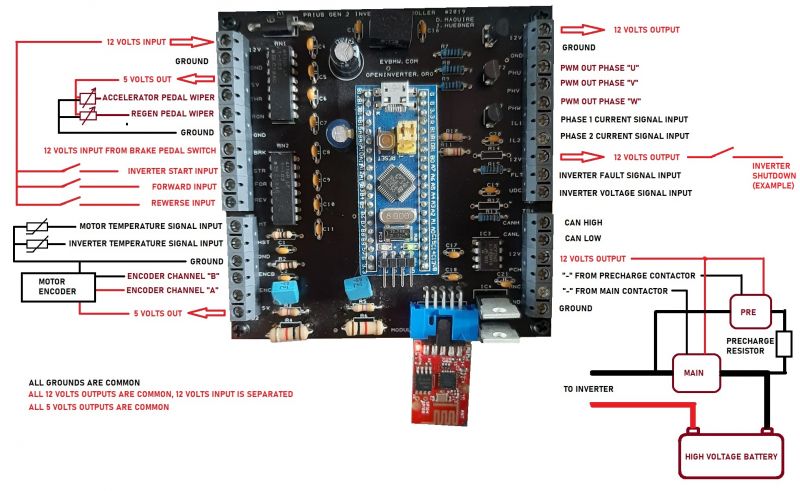
Hurray, new diagram!
Some feedback:
- You deleted the info about how to hook up the wires to the pins on the inverter cable. That's helpful information to many people.
- Your brake line input goes nowhere...
- Your "start" is a lever switch, which, I think it should instead be a momentary pushbutton (it's momentary, right? not latching on?).
- Are the Start/Forward/Reverse supposed to tie into the 12v input? Or the smoothed and polarity-checked 12v output? I thought the only thing that should go directly to the 12v input is the board itself, everything else should connect to the cleaned up supply after that.
Also, I want to thank you for pushing forward with your build. I've basically sat on mine for 5 months now because I was tired of asking dumb questions and blundering through making more mistakes than correct guesses. Your progress and troubleshooting has been inspiring and confidence-boosting for me.
-
konstantin8818
- Posts: 287
- Joined: Sun Jan 19, 2020 2:33 pm
- Location: Minsk, Belarus
- Been thanked: 5 times
Re: Toyota Prius Gen 2 Inverter Controller
1. Will add pin numbers.MattsAwesomeStuff wrote: ↑Sat Jul 04, 2020 6:41 am Some feedback:
- You deleted the info about how to hook up the wires to the pins on the inverter cable. That's helpful information to many people.
- Your brake line input goes nowhere...
- Your "start" is a lever switch, which, I think it should instead be a momentary pushbutton (it's momentary, right? not latching on?).
Also, I want to thank you for pushing forward with your build. I've basically sat on mine for 5 months now because I was tired of asking dumb questions and blundering through making more mistakes than correct guesses. Your progress and troubleshooting has been inspiring and confidence-boosting for me.
2. From Damien's table I see It comes from brake light switch, so it means this input from car 12v system. I believe in EV 12V line must be pretty stable, keeping in mind there is no alternator, but DC-DC converter of inverter itself provides stabilised power.
3. Is anywhere written that inverter start must be a button? (I've seen Damien's latest video where he pushes start button)
In a few days I'll continue this process, when I'll buy coolant pump and additional battery - need MORE POWAH!
- загружено.jpg (9.48 KiB) Viewed 3365 times
-
RetroZero
- Posts: 731
- Joined: Tue Oct 29, 2019 2:48 pm
- Location: France
- Has thanked: 329 times
- Been thanked: 44 times
- Contact:
Re: Toyota Prius Gen 2 Inverter Controller
Yes, great that you're carrying on and updating the wiki too.
From what I remember, the preharge resistor comes AFTER the contacter in direction to the inverter..
I would suggest changing the colours around too for the hv lines.
À newbie would wire it all up to the negative, and positive without preharge.
I haven't got as far as you, so I would hope someone else backs me up, or knocks me over the head, cause I got it backwards.
From what I remember, the preharge resistor comes AFTER the contacter in direction to the inverter..
I would suggest changing the colours around too for the hv lines.
À newbie would wire it all up to the negative, and positive without preharge.

I haven't got as far as you, so I would hope someone else backs me up, or knocks me over the head, cause I got it backwards.

-
konstantin8818
- Posts: 287
- Joined: Sun Jan 19, 2020 2:33 pm
- Location: Minsk, Belarus
- Been thanked: 5 times
Re: Toyota Prius Gen 2 Inverter Controller
I'm that newbie who connected precharge to negative line. It was in negative line on Prius junction box. So I've decided to do the same. It works fine so far. I just don't know is there any difference where load is connected to? Load is load, capacitor is capacitor. Any suggestions from electronics engineers?RetroZero wrote: ↑Sat Jul 04, 2020 10:35 am Yes, great that you're carrying on and updating the wiki too.
From what I remember, the preharge resistor comes AFTER the contacter in direction to the inverter..
I would suggest changing the colours around too for the hv lines.
À newbie would wire it all up to the negative, and positive without preharge.
I haven't got as far as you, so I would hope someone else backs me up, or knocks me over the head, cause I got it backwards.
And about newbies being confused by the drawing: if person decided to go that deep into high voltage electronics, I bet he have got some knowledge and common sense, otherwise I'm afraid to imagine how many things can go wrong...
-
RetroZero
- Posts: 731
- Joined: Tue Oct 29, 2019 2:48 pm
- Location: France
- Has thanked: 329 times
- Been thanked: 44 times
- Contact:
Re: Toyota Prius Gen 2 Inverter Controller
Ahh, that's interesting that toyota wired up on negative side. I need to dig into that.
I thought there was something about charging the capacitors 'gently' via preharge relay an resistor. I suppose via the negative can be done too. Will have to go back to my theory books.
I thought there was something about charging the capacitors 'gently' via preharge relay an resistor. I suppose via the negative can be done too. Will have to go back to my theory books.
-
MattsAwesomeStuff
- Posts: 898
- Joined: Fri Apr 26, 2019 5:40 pm
- Has thanked: 291 times
- Been thanked: 177 times
Re: Toyota Prius Gen 2 Inverter Controller
My point is that, wherever it goes, it should be in the diagram. Otherwise someone is going to ask "Where does that connect to?" and the answer is not there.konstantin8818 wrote: ↑Sat Jul 04, 2020 7:45 am 2. From Damien's table I see It comes from brake light switch, so it means this input from car 12v system.
Well, the board has polarity a polarity protection diode, and an input and output for a reason.I believe in EV 12V line must be pretty stable, keeping in mind there is no alternator, but DC-DC converter of inverter itself provides stabilised power.
It's okay for you to skip it, if you're aware of that, but the diagram explaining to a novice how to wire the board should probably wire it the correct way.
Whether it has to be a button or some other momentary switch (there are momentary lever switches that spring back to a neutral position) does not matter no.3. Is anywhere written that inverter start must be a button? (I've seen Damien's latest video where he pushes start button)
Whether the switch has to be momentary at all or whether it will still work correctly when latched... I'm not sure. I'm not sure if you'd get weird behavior from it if it wasn't expected to be on.
In my understanding the purpose was to emulate the "engage the starter motor" springy position on the keyswitch that cars have. You'd never drive around with the starter engaged the whole time.
Again, it might work for you, your choice, but the diagram that explains it to everyone should follow the intended operation. They also have latching pushbuttons (for example, the power button on cheap desktop speakers), but, generally I think most people see lever as latching, pushbutton as momentary in a diagram so that's good shorthand to use.
...
Also, the Forward/Reverse switch should probably be a SPDT switch (ideally with a dead neutral position). The diagram right now shows that you could engage both forward and reverse at the same time which is not how you'd think about a selector switch.
-
konstantin8818
- Posts: 287
- Joined: Sun Jan 19, 2020 2:33 pm
- Location: Minsk, Belarus
- Been thanked: 5 times
Re: Toyota Prius Gen 2 Inverter Controller
Well, at the moment I'm using switch. When I engage it, precharge deactivates, main for some reason doesn't activates. However, PWM is working, and it is working when I deactivate switch, which means that might be temporary indeed. It is just me who didn't get the logic.MattsAwesomeStuff wrote: ↑Sat Jul 04, 2020 4:59 pm In my understanding the purpose was to emulate the "engage the starter motor" springy position on the keyswitch that cars have. You'd never drive around with the starter engaged the whole time.
Again, it might work for you, your choice, but the diagram that explains it to everyone should follow the intended operation. They also have latching pushbuttons (for example, the power button on cheap desktop speakers), but, generally I think most people see lever as latching, pushbutton as momentary in a diagram so that's good shorthand to use.
...
Also, the Forward/Reverse switch should probably be a SPDT switch (ideally with a dead neutral position). The diagram right now shows that you could engage both forward and reverse at the same time which is not how you'd think about a selector switch.
Anyway I've already updated picture with pushbutton.
About forward/reverse: even in Curtis manual forward/rewerse are shown as separated switches, not as SPDT. Besides, I've already found out that if both activated - nothing happens, car doesn't move.
... holy cow, we are getting back to a problem of common sense...
EDIT
-
Isaac96
- Posts: 656
- Joined: Sat Oct 05, 2019 6:50 pm
- Location: Northern California, USA
- Been thanked: 1 time
- Contact:
Re: Toyota Prius Gen 2 Inverter Controller
I don't think that is supposed to happen...konstantin8818 wrote: ↑Sat Jul 04, 2020 6:16 pm The most interesting thing with this board that it doesn't control "MG shutdown" pin of inverter... As soon as you switch the board on, but didn't pushed "start" botton yet, you can select direction and press pedal, unfortunately insteard of moving you'll burn precharge wiring...
PWM output is only supposed to be possible in opmode 1 or 2 (normal or manual mode).
Can you try looking at the opmode with board switched on but not started? Maybe you have a wire crossed somewhere.
-Isaac
-
konstantin8818
- Posts: 287
- Joined: Sun Jan 19, 2020 2:33 pm
- Location: Minsk, Belarus
- Been thanked: 5 times
-
konstantin8818
- Posts: 287
- Joined: Sun Jan 19, 2020 2:33 pm
- Location: Minsk, Belarus
- Been thanked: 5 times
Re: Toyota Prius Gen 2 Inverter Controller
OK, I checked it and all works fine. When logic board is switched ON, opmode is "0" and it doesn't react to direction switch and pedal. Inverter start botton is momentary - as soon as it was pressed, opmode is "1" and it only swithes OFF when logic board is switched OFF.
MAIN didn't closed because of no contact on blue pill board
-
konstantin8818
- Posts: 287
- Joined: Sun Jan 19, 2020 2:33 pm
- Location: Minsk, Belarus
- Been thanked: 5 times
Re: Toyota Prius Gen 2 Inverter Controller
Damien is a true 80 lvl troll  Also for some reason FLT pin missing as well. Damien can you please tell why?
-
konstantin8818
- Posts: 287
- Joined: Sun Jan 19, 2020 2:33 pm
- Location: Minsk, Belarus
- Been thanked: 5 times
Re: Toyota Prius Gen 2 Inverter Controller
Ok, problem is still there 
Before strt button pressed there is 3.15 volts on precharge pin, and 2.4 volts on dcsw pin of blue pill. When strt is pressed, precharge is deactivated, there is zero volts, but on dcsw there is still 2.4 volts. I'm confused.
As soon as strt pressed there is derate error occurs - current limit. What could be the problem?